Installation
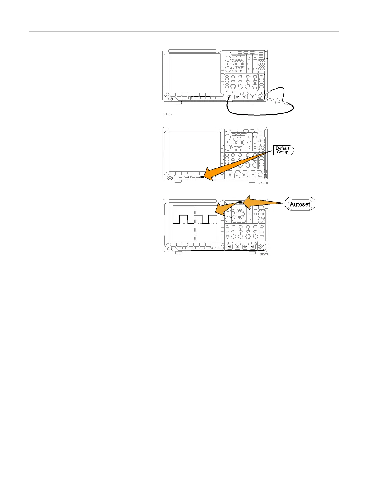
3. Connect the probe connector to
oscilloscope channel 1 and the probe tip
and reference
lead to the PROBE COMP
terminals on the oscilloscope front panel.
4. Push Default Setup.
5. Push Autoset. The screen should now
display a
square wave, approximately
2.5 V at 1 kHz.
If the signal appears but is misshapen,
perform
the procedures for compensating
the probe. (See page 14, Compensating
a non-TPP0500 or non-TPP1000
Passive
Voltage Probe.)
If no signal appears, rerun the procedure.
If this does not remedy the situation,
have th
e instrument serviced by qualified
service personnel.
Compensating a TPP0500 or TPP1000 Passive Voltage Probe
The MDO4000 Series oscilloscopes can automatically compensate TPP0500 and TPP1000 probes. This e liminates the need
for manual probe compensation, as is typically performed with other probes.
Each compensation generates values for a specifi c probe and channel combination. If you want to use the probe on another
channel and desire to compensate the new probe-channel pair, you must run a new set of compensation steps for that new
combination.
1. Connect the oscilloscope power cable. (See
page 10, Powering on the Oscilloscope .)
2. Power on the oscilloscope.
12 MDO4000 Series Oscilloscopes User Manual
 Loading...


