Installation
TPP1000
Probe
Setup
SN:
000001
Atten: 10X
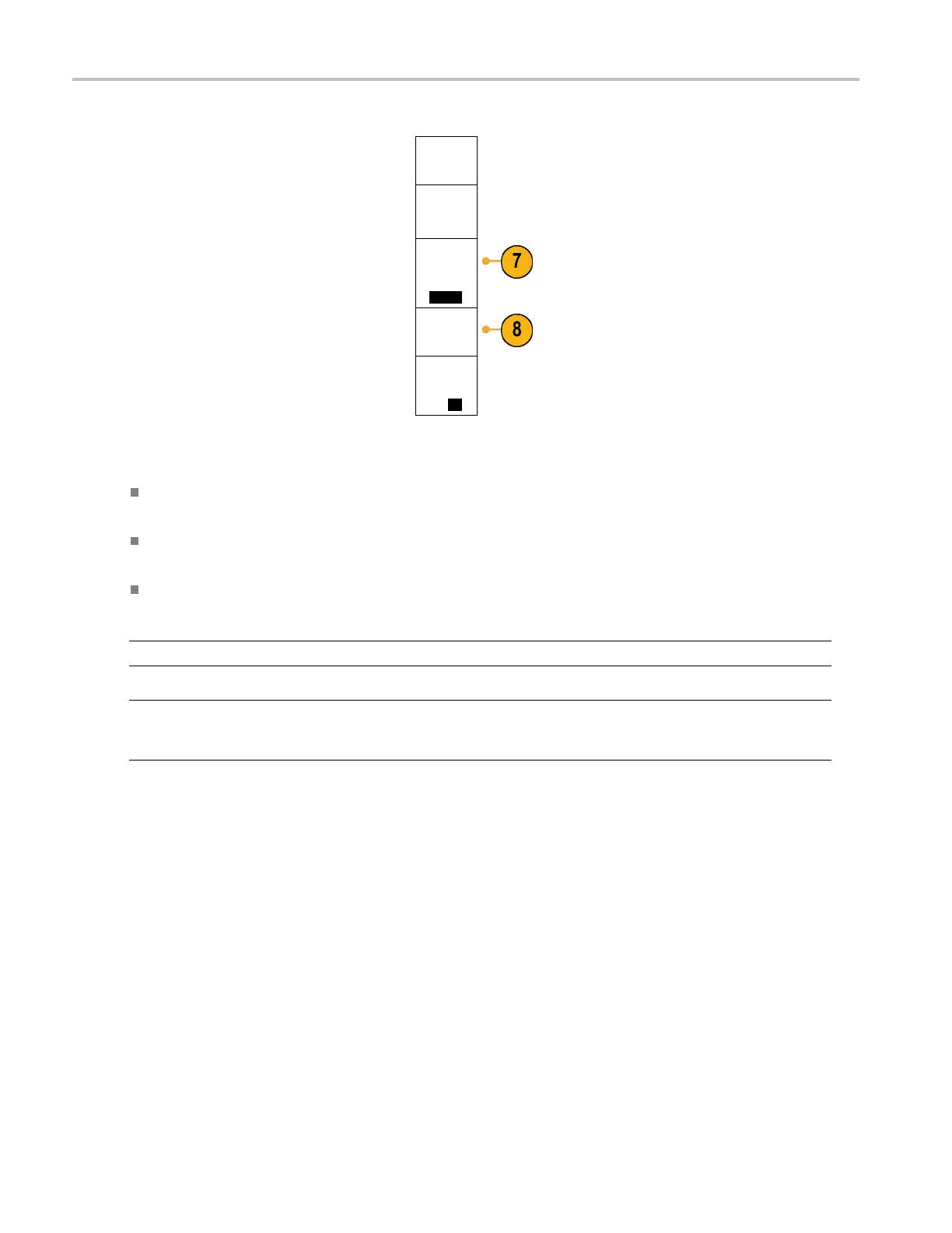
7. Notice that the compensation status starts
as Default.
Compen-
sation
Status
Default
8. Push Compens
ate probe and follow the
instructions that appear on the display.
Compen-
sate probe
for 1
Measure
Current
Yes|
No
When compensating TPP0500/TPP1000 probes on the M DO 4000 Series oscilloscopes:
Each compensation generates values for a specific probe and channel combination. If you want to use the probe on
another ch
annel and desire to compensate the new probe-channel pair, you must run a new set of compensation steps.
Each chann
el can s tore compensation values for 10 individual probes. If you try to c ompensate an 11th probe on a
channel, the oscilloscope will delete the values for the least recently used probe and add the values for the new probe.
The oscilloscope will assign default compensation values to a TPP0500 or TPP1000 probe connected to the Aux
In channel.
NOTE. Af
actory calibration will delete all stored compensation values
NOTE. A probe compensation failure is most likely due to intermittent connection of the probe tip or ground connection
during the probe compensation operation. If a failure occurs, the oscilloscope will re-use the old probe compensation values,
if they
existed prior to the failed probe compensation operation.
Compe
nsating a non-TPP0500 or non-TPP1000 Passive Voltage Probe
Whenever you attach a passive voltage probe for the first time to any input channel, compensate the probe to match it to
the corresponding oscilloscope input channel.
If you are interested in using the automatic probe compensat ion procedure described above for the TPP0500 and TPP1000 probes
(See page 12, Compensating a TPP0500 or TPP1000 Passive Voltage Probe.) on a non-TPP0500/TP P1000 Tektronix passive
probe, check the instruction manual for your probe to see if it qualifies. Otherwise, to properly compensate your passive probe:
1. Follow the steps for the functional
check. (See page 11, Functional
Check.)
14 MDO4000 Series Oscilloscopes User Manual
 Loading...


