Acquire the Sign
al
2. Push Trigger Me
nu and enter trigger
parameters. (See page 83, Choosing a
Trigger Type.)
You can displa
y bus information without
triggering on the bus signal.
SettingUpBu
s Parameters
NOTE. For m ost bus sources, you may use any combination of channels 1 through 4, and D15 through D0. With some
buses, you may also use Ref 1 through 4 and Math as sources for protocol decode.
To trigger
on serial or parallel bus conditions, refer to Triggering on Buses. (See page 86, Triggering on Buses.)
To set up bus parameters:
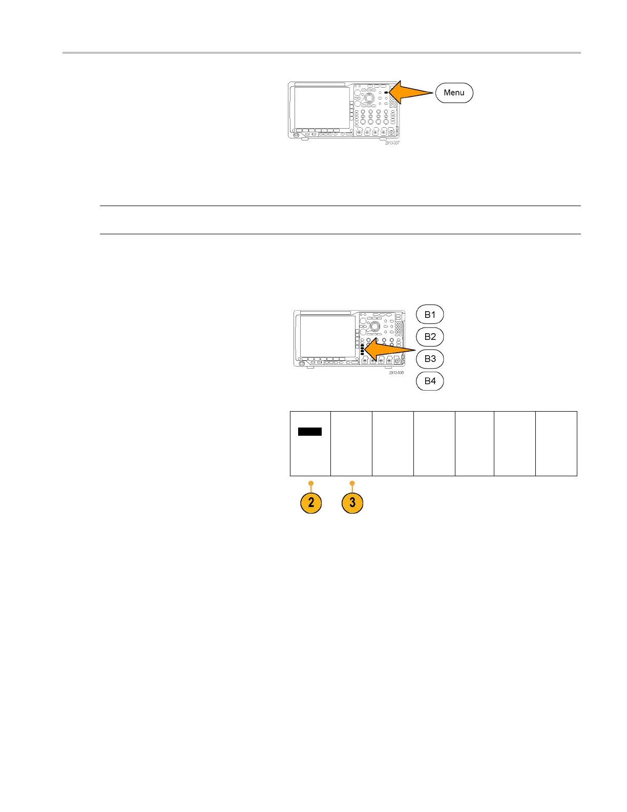
1. Push B1, B2
, B3,orB4 to bring u p the
lower-bezel bus menu.
2. Push Bus. Turn multipurpose knob a to
scroll through the list of bus types and select
the desired bus: Parallel, I
2
C, SPI, RS-232,
CAN, LIN, FlexRay, Audio, US B, Ethernet, or
MIL-STD-1553.
Bus B1
Parall
el
Define
Inputs
Thresholds B1 Label
Parallel
Bus
Display
Event
Table
The actual menu items shown will depend on
your model oscilloscope and the application
modules installed.
3. Push Define Inputs. The choices depend
on the selected bus.
MDO4000 Series Oscilloscopes User Manual 61
 Loading...


