Section
6-PS
501
0
MAINTENANCE
GENERAL MAINTENANCE INFORMATION
Bus Address Switch
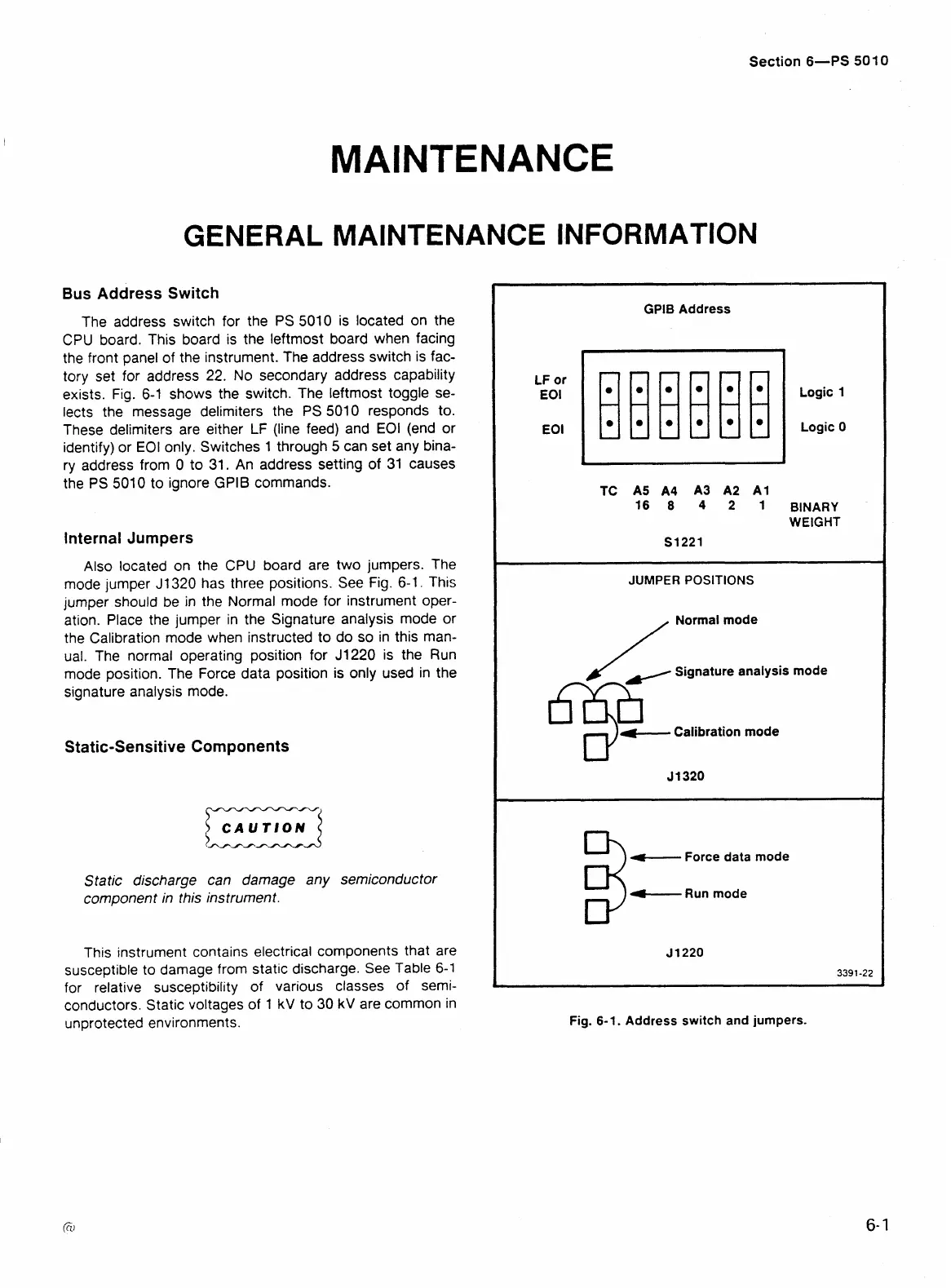
The address switch for the PS 5010 is located on the
CPU board. This board is the leftmost board when facing
the front panel of the instrument. The address switch is fac-
tory set for address
22.
No secondary address capability
exists.
Fig.
6-1 shows the switch. The leftmost toggle se-
lects the message delimiters the
PS
5010 responds to.
These delimiters are either
LF
(line feed) and EOI (end or
identify) or EOI only. Switches 1 through
5
can set any bina-
ry address from 0 to 31. An address setting of 31 causes
the
PS
501
0
to ignore GPlB commands.
Internal Jumpers
Also located on the CPU board are two jumpers. The
mode jumper J1320 has three positions. See
Fig.
6-1.
This
jumper should be in the Normal mode for instrument oper-
ation. Place the jumper in the Signature analysis mode or
the Calibration mode when instructed to do so in this man-
ual. The normal operating position for
J1220 is the Run
mode position. The Force data position is only used in the
signature analysis mode.
Static-Sensitive Components
Static discharge can damage any semiconductor
component in this instrument.
This instrument contains electrical components that are
susceptible to damage from static discharge. See Table
6-1
for relative susceptibility of various classes of semi-
conductors. Static voltages of 1
kV
to 30
kV
are common in
unprotected environments.
LF
or
EOI
EOI
GPlB Address
Logic
1
Logic 0
BINARY
WEIGHT
S1221
JUMPER
POSITIONS
/
Normal mode
)/
Signature analysis mode
4-,
Calibration mode
Force data mode
rC----
Run mode
Fig. 6-1. Address switch and jumpers.
 Loading...


