Operating Instructions-PS
501
0
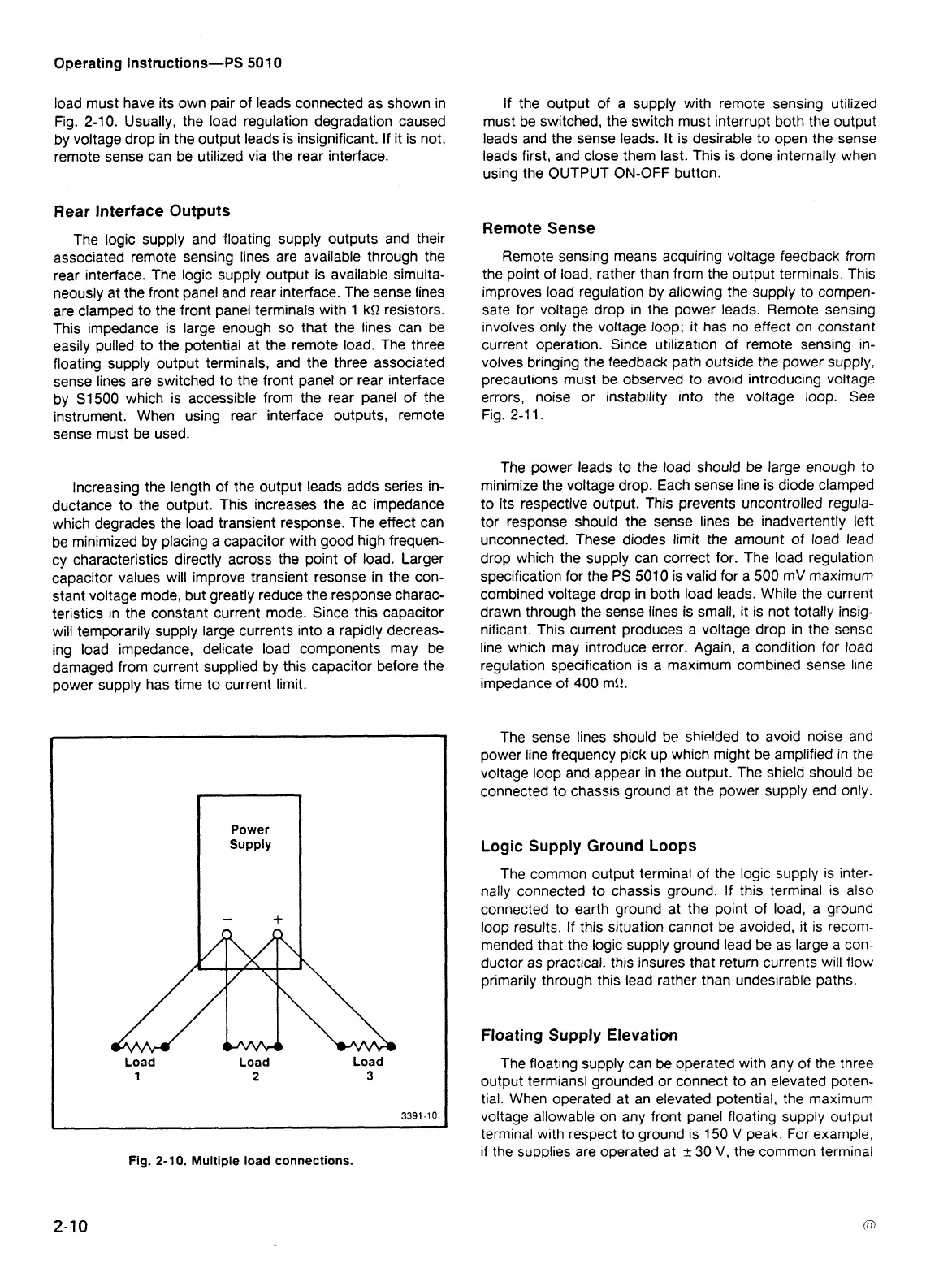
load must have its own pair of leads connected as shown in
Fig. 2-10. Usually, the load regulation degradation caused
by voltage drop in the output leads is insignificant. If it is not,
remote sense can be utilized via the rear interface.
Rear Interface Outputs
The logic supply and floating supply outputs and their
associated remote sensing lines are available through the
rear interface. The logic supply output is available simulta-
neously at the front panel and rear interface. The sense lines
are clamped to the front panel terminals with 1
kQ resistors.
This impedance is large enough so that the lines can be
easily pulled to the potential at the remote load. The three
floating supply output terminals, and the three associated
sense lines are switched to the front panel or rear interface
by S1500 which is accessible from the rear panel of the
instrument. When using rear interface outputs, remote
sense must be used.
Increasing the length of the output leads adds series in-
ductance to the output. This increases the ac impedance
which degrades the load transient response. The effect can
be minimized by placing a capacitor with good high frequen-
cy characteristics directly across the point of load. Larger
capacitor values will improve transient resonse in the con-
stant voltage mode, but greatly reduce the response charac-
teristics in the constant current mode. Since this capacitor
will temporarily supply large currents into a rapidly decreas-
ing load impedance, delicate load components may be
damaged from current supplied by this capacitor before the
power supply has time to current limit.
Power
Supply
-
+
Load
1
Load Load
2
3
3391-10
Fig.
2-
10.
Multiple load connections.
If the output of a supply with remote sensing utilized
must be switched, the switch must interrupt both the output
leads and the sense leads. It is desirable to open the sense
leads first, and close them last. This is done internally when
using the OUTPUT ON-OFF button.
Remote
Sense
Remote sensing means acquiring voltage feedback from
the point of load, rather than from the output terminals. This
improves load regulation by allowing the supply to compen-
sate for voltage drop in the power leads. Remote sensing
involves only the voltage loop; it has no effect on constant
current operation. Since
utilization of remote sensing in-
volves bringing the feedback path outside the power supply,
precautions must be observed to avoid introducing voltage
errors, noise or instability into the voltage loop.
See
Fig. 2-1 1.
The power leads to the load should be large enough to
minimize the voltage drop. Each sense line is diode clamped
to its respective output. This prevents uncontrolled regula-
tor response should the sense lines be inadvertently left
unconnected. These diodes limit the amount of load lead
drop which the supply can correct for. The load regulation
specification for the
PS
501 0 is valid for
a
500
mV maximum
combined voltage drop in both load leads. While the current
drawn through the sense lines is small, it is not totally insig-
nificant. This current produces a voltage drop in the sense
line which may introduce error. Again, a condition for load
regulation specification is a maximum combined sense line
impedance of 400
mQ.
The sense lines should
be
shielded to avoid noise and
power line frequency pick up which might be amplified in the
voltage loop and appear in the output. The shield should be
connected to chassis ground at the power supply end only.
Logic Supply Ground Loops
The common output terminal of the logic supply is inter-
nally connected to chassis ground. If this terminal is also
connected to earth ground at the point of load, a ground
loop results. If this situation cannot be avoided, it is recom-
mended that the logic supply ground lead be as large
a
con-
ductor as practical. this insures that return currents will flow
primarily through this lead rather than undesirable paths.
Floating Supply Elevation
The floating supply can be operated with any of the three
output termiansl grounded or connect to an elevated poten-
tial. When operated at an elevated potential, the maximum
voltage allowable on any front panel floating supply output
terminal with respect to ground
is
150
V
peak. For example,
if the supplies are operated at
+-
30
V,
the common terminal
 Loading...


