Section
1
-PS
58
10
SPECIFICATION
Introduction
This PS 5010 Programmable Power Supply provides a
floating dual supply and a ground referenced logic supply.
Each supply has independent constant voltage or constant
current modes with automatic crossover.
The floating supply provides 0 to +32 Vdc and 0 to
-32 Vdc, both with respect to a common front panel termi-
nal. All floating supply terminals may be elevated above
ground to a maximum 150 V peak. Voltages from
0 to 64 V
are available across the dual supply terminals. When the
PS. 501 0 is installed in a TM 5000 series power module with
one high power compartment, currents to 750
mA (from 0 to
32
V) and 1.6 A (from
0
to 15 V) are available. When the
PS
5010 is installed in two low power compartments of the
TM 5000 series power module, currents to 400 mA (from 0
to 32 V) and 750 MA (from 0 to 15 V) are available. The
floating supplies are programmable in increments of 10
mV
from 0 to 10.0
V
and in increments of 100 mV from 10.1 V
to 32.0 V. The current programmed in 50 mA increments
from 50 mA to 1.6 A.
The logic supply provides 4.5 Vdc to 5.5 Vdc at currents
to 3 A. The logic supply is programmable in increments of
10 mV from 4.50 V to 5.50 V and in current increments of
100 mA over a range of 100 mA to 3.0 A.
The front panel LED display is divided into three sections.
Each section indicates the programmed current or voltage
for one supply. Each display contains a three digit seg-
mented numeric LED display and two separate LEDs. These
LEDs are located at the bottom of the numeric displays.
They indicate whether voltage or current is being displayed.
In the operating mode, the display show the true output
voltage in constant voltage mode or current in the constant
current mode. Since the display parameter changes with the
automatic crossover the displays always indicate the true
output values.
Complete information for programming the PS 5010 via
the GPIB is found in the Programming section of this man-
ual. A sample program is provided in the Programming sec-
tion to verify the operation of the instrument on the GPIB.
NOTE
All references to the
SA
501 in this manual now apply
to the
067-
1
099-00
Signature Analyzer.
NOTE
The
PS
50 10 operates only in
a
TM 5000 series
power module.
lEEE
488
(GPIB)
Function
Capability
The PS 5010 is programmable via the digital interface
specified in IEEE Standard 488-1978, "Standard Digital In-
terface for Programmable Instrumentation". In this manual,
the interface is commonly called the General Purpose Inter-
face Bus (GPIB).
The
IEEE Standard identifies the interface function reper-
toire of an instrument on the GPIB in terms of interface func-
tion subsets. The subsets are defined in the standard. The
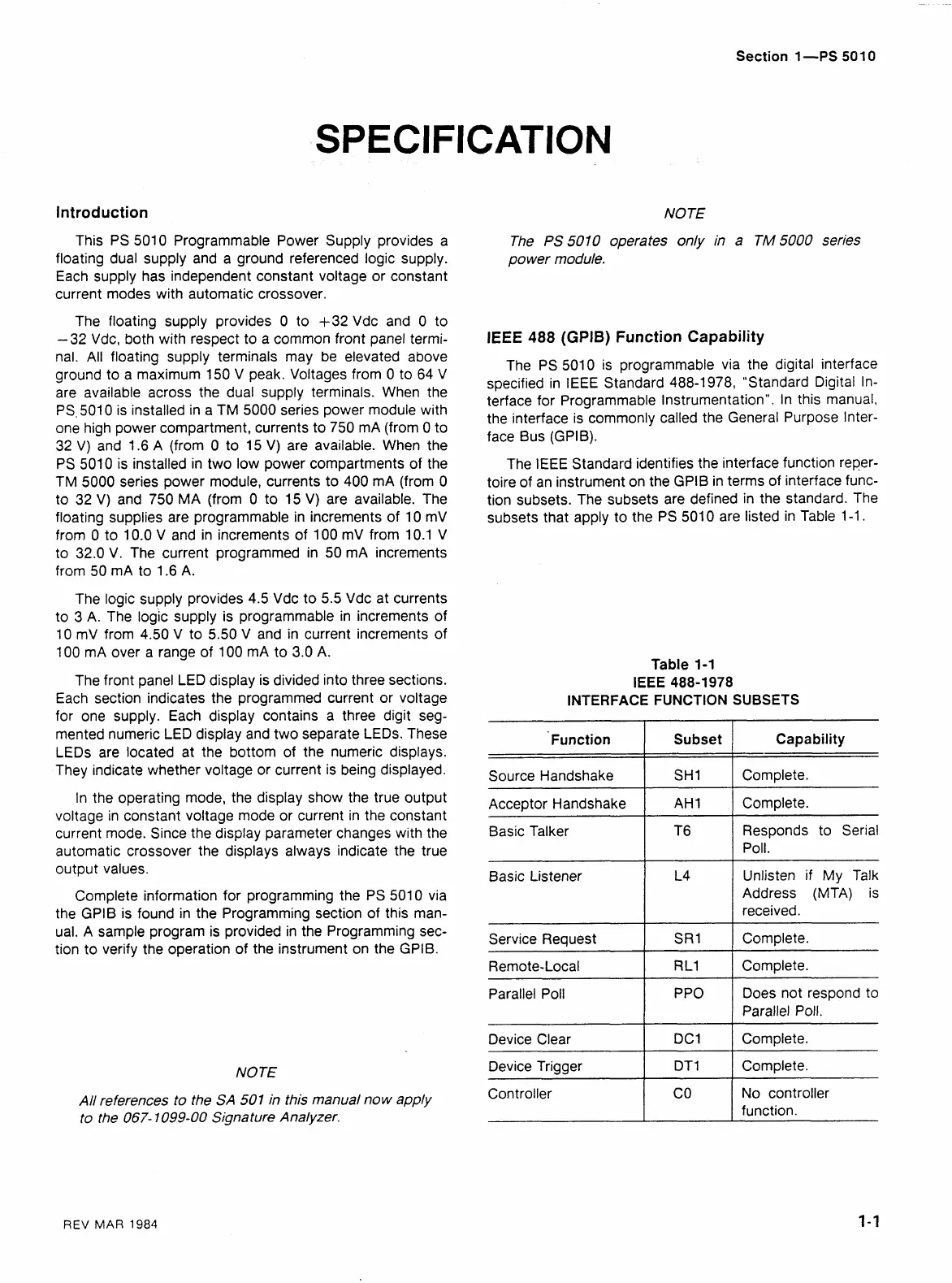
subsets that apply to the PS 501 0 are listed in Table 1-1.
Table 1-1
IEEE 488-1 978
INTERFACE FUNCTION SUBSETS
--
-
Acceptor Handshake
I
AH1
1
Complete.
--
-
Basic Talker
Capability
Complete.
Function
Source Handshake
Basic Listener
__1
Subset
SH1
T6
1
Responds to Serial
Poll.
Unlisten if
My
Talk
Address (MTA) is
received.
1
t;;
1
complete.
Service Request
Remote-Local
Complete.
Parallel Poll PPO Does not respond to
Parallel Poll.
1
!:;
1
Complete.
Device Clear
Device Trigger Complete.
Controller No controller
function.
REV
MAR
1984
 Loading...


