Section
3-PS
501 0
PROGRAMMING
Introduction
This section of the manual provides information for pro-
gramming the PS 5010 by remote control via the digital in-
terface.
In this manual the digital interface is called the IEEE-
488
General Purpose Interface Bus (GPIB). The following
information assumes the reader is knowledgeable
in
GPlB
communications and has some exposure to programming
controllers. Communication via the GPlB is specified and
described in the IEEE Standard 488-1 978, Standard Digital
Interface for Programmable
lnstrumentationl.
TM
5000 in-
struments are designed to communicate with any GPIB-
compatible controller that sends and receives
ASCII
messages (commands) over the GPIB. These commands
program the instrument or request information from the
instrument.
Commands for TM 5000 programmable instruments are
designed for compatabilty among instrument types. The
same command is used in different instruments to control
similar functions. In addition, commands are specified in
mnemonics related to the functions they implement. For ex-
ample, the command
INIT initializes instrument settings to
their power-up states. For further ease of programming,
command mnemonics match those on the front panel.
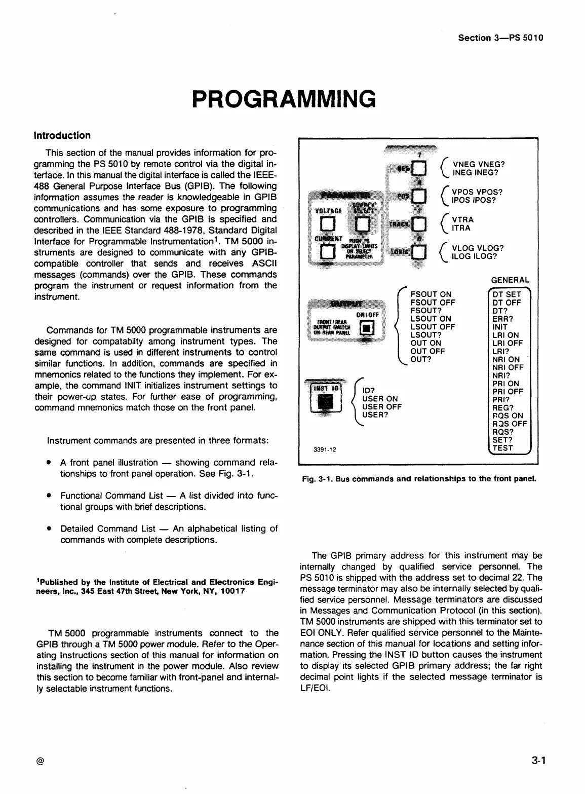
Instrument commands are presented in three formats:
A front panel illustration
-
showing command rela-
tionships to front panel operation. See Fig.
3-1.
Functional Command List
-
A
list divided into func-
tional groups with brief descriptions.
Detailed Command List
-
An alphabetical listing of
commands with complete descriptions.
'Published by the Institute
of
Electrical and Electronics Engi-
neers,
Inc.,
345
East 47th Street, New York,
NY,
1001
7
TM
5000 programmable instruments connect to the
GPlB through a
TM
5000 power module. Refer
to
the Oper-
ating Instructions section of this manual for information on
installing the instrument in the power module. Also review
this section to become familiar with front-panel and internal-
ly selectable instrument functions.
VNEG VNEG?
INEG INEG?
f
FSOUT ON
VPOS VPOS?
IPOS IPOS?
VTRA
ITRA
VLOG VLOG?
ILOG ILOG?
FSOUT OFF
FSOUT?
LSOUT ON
LSOUT OFF
LSOUT?
OUT ON
USER ON
USER OFF
USER?
GENERAL
r
DT SET
DT OFF
DT?
ERR?
INIT
LRI ON
LRI OFF
LRI?
NRI ON
NRI OFF
NRI?
PRI ON
PRI OFF
PR I?
REG?
PQS ON
R2S OFF
RQS?
SET?
TEST
1
Fig. 3-1. Bus commands and relationships to the front panel.
The GPIB primary address for this instrument may
be
internally changed by qualified service personnel. The
PS
5010 is shipped with the address set to decimal
22.
The
message terminator may also
be
internally selected by quali-
fied service personnel. Message terminators are discussed
in Messages and Communication Protocol (in this section).
TM 5000 instruments are shipped with this terminator set to
EOI ONLY. Refer qualified service personnel to the Mainte-
nance section of this manual for locations and setting infor-
mation. Pressing the
INST ID button causes the instrument
to display its selected GPlB primary address; the far right
decimal point lights if the selected message terminator is
LFIEOI.
 Loading...


