them back into the board with a socket wrench that con-
tacts the periphery (case) of the switch. If pressure is ap-
plied to the clear plastic near the center of the switch the
switch may come apart. Once apart the switch is difficult to
reassemble.
terconnect board
remove this screw
and the one on the
opposite side.
ing the Intercon-
nect board.
3391
-25
Fig. 6-4. Interface board removal.
GENERAL
TROUBLESHOOTING
Troubleshooting Information
Generally, locating a problem area in the PS 501 0 circuits
is straightforward. Review the related section of the detailed
circuit description as an aid. Some subtle problems may af-
fect circuits not apparently related, or may not show up
while performing the Performance Check Procedure. As an
aid in locating some of these problem areas, the following
descriptions and tests are provided.
CPU
Board
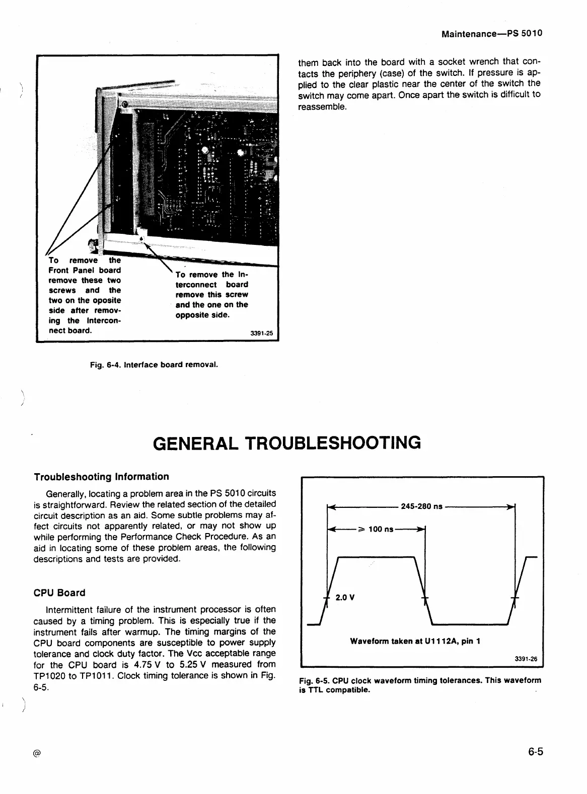
Intermittent failure of the instrument processor is often
caused by a timing problem. This is especially true if the
instrument fails after warmup. The timing margins of the
CPU board components are susceptible to power supply
tolerance and clock duty factor. The Vcc acceptable range
for the CPU board is 4.75
V
to 5.25
V
measured from
TP1020 to TP1011. Clock timing tolerance is shown in
Fig.
6-5.
Waveform taken at
U1112A,
pin
1
Fig. 6-5.
CPU
clock waveform timing tolerances.
This
waveform
is
TTL
compatible.
 Loading...


