TCPA300 and TCPA400 Performance Verification
5-12
TCPA300/400 Amplifiers and TCP300/400 Series Current Probes Instruction Manual
AC Coupling
The following test checks that the AC coupling circuit of the amplifier functions
properly. First, you measure a square-wave signal in DC coupling mode and
record the value, and then switch to AC coupling and measure the signal
amplitude.
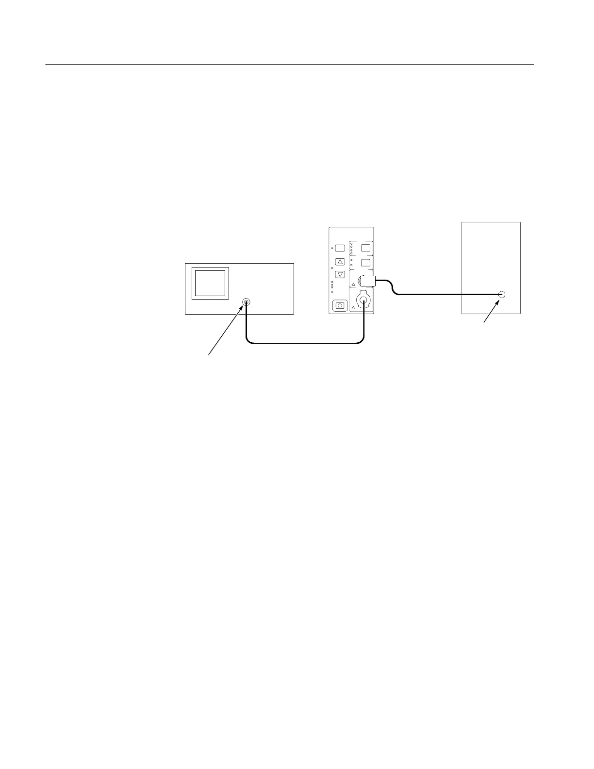
Square wave
generator
Output
Test oscilloscope
Amplifier
TekProbe interface cable or
50 ohm coaxial cable
Calibration
adapter
50 Ω oscilloscope input -- use the TekProbe
InterfaceCableorusea50Ω cable. (Add
50 Ω termination here if oscilloscope has
only high-impedance input.)
Note: If using a Wavetek 9100,
use the Output connector on the
front of the instrument.
Figure 5- 4: AC coupling test setup
To perform the check, do the following:
1. Connect the circuit as shown in Figure 5--4.
2. Set the amplifier COUPLING to DC.
3. If you are checking a TCPA300, set the RANGE to 1A/V.
4. Set the generator to output a 28 Hz square wave.
5. Set the oscilloscope horizontal scale to 4 or 5 ms/div.
6. Use Table 5--9 on page 5--13 to make further equipment settings.
7. Measure the signal on the oscilloscope and verify that it is 1Vp--p. If
necessary, adjust the generator output to achieve 1Vp-p.
8. Set the amplifier COUPLING to AC.
9. Measure the signal on the oscilloscope and verify that the signal is within the
limits on the test record.
 Loading...

