TCPA300 and TCPA400 Performance Verification
TCPA300/400 Amplifiers and TCP300/400 Series Current Probes Instruction Manual
5-7
3. Make or verify the equipment settings in Table 5--4:
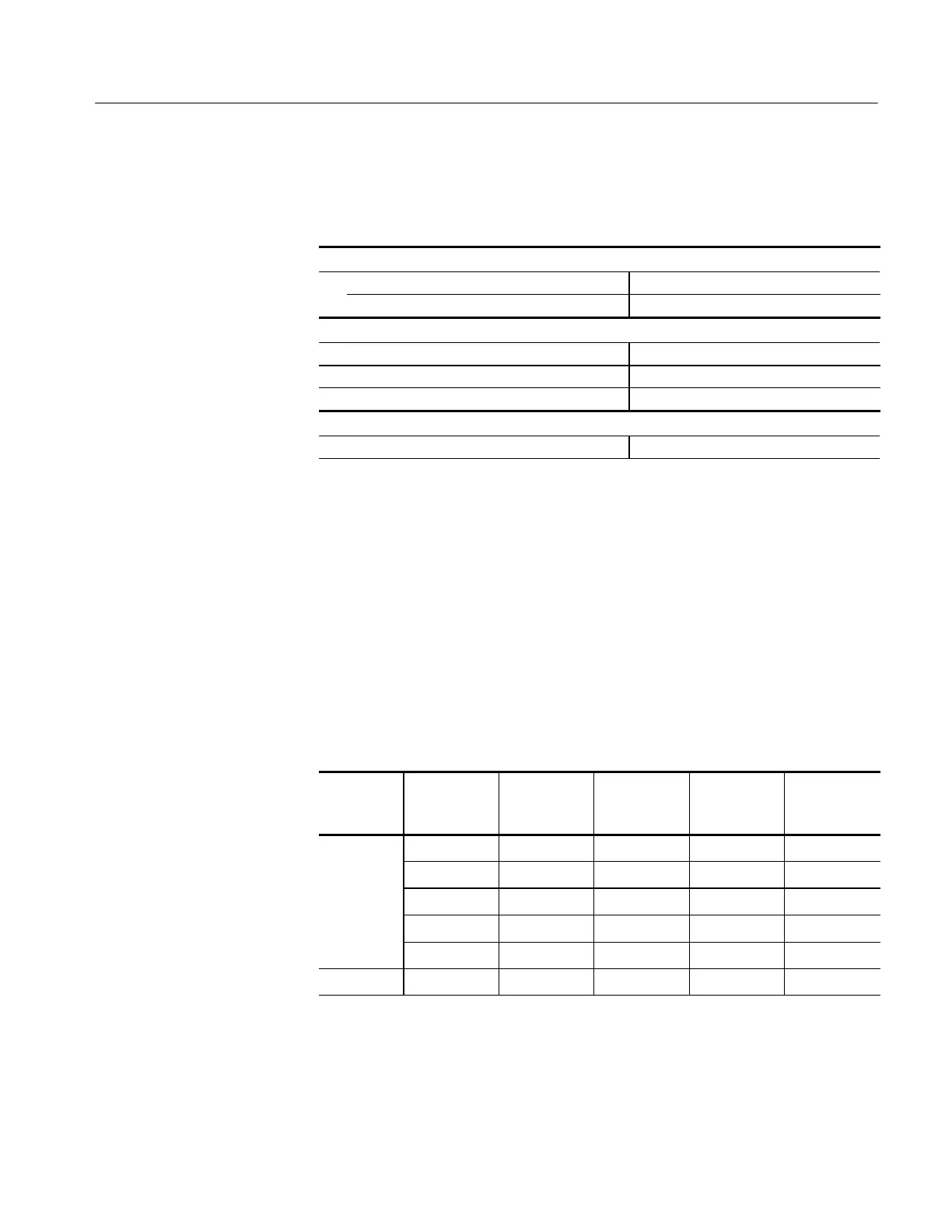
Table 5- 4: Equipment settings
Digital multimeter
Measurement Ty pe DC volts
Range Autoranging
Current source
Voltage 6V
Current 100 mA
Output Off
TCPA300 and TCPA400 amplifier
Coupling DC
After the equipment is set up, proceed as follows:
4. Connect the Calibration Adapter to the PROBE INPUT of the amplifier.
5. For each of the Range settings in Table 5--5, perform the following steps:
a. If you are checking a TCPA300, set the amplifier to the desired Range
setting in Table 5--5.
b. Enable the output of the current source.
c. Record the exact measurement of the digital multimeter as M
1
.
Table 5- 5: DC gain accuracy test for the TCPA300 and TCPA400
Amplifier Range, A/V
Current
source out-
put
Expected
output, V
E
(VDC)
Measured
output, M
1
(VDC)
% Error,
calculated
TCPA300 1 100 mA 5.0000
5 100 mA 2.5000
10 100 mA 1.2375
50 100 mA 0.4835
50 (COMP)
1
100 mA 0.4585
TCPA400 1A/mV 100 mA 2.5000
1
Both 10 A/V and 50 A/V RANGE LEDs light.
Procedure
 Loading...

