TCP305 and TCP312 Performance Verification
5-26
TCPA300/400 Amplifiers and TCP300/400 Series Current Probes Instruction Manual
The system rise time (t
r
system) is the rise time of the displayed signal when
output of the pulse generator is connected directly to the oscilloscope input.
(The current probe and amplifier are excluded.)
7. Verify that the probe rise time is less than the warranted specification listed
in the test record.
8. Record the results on the test record.
9. Disconnect the probe from the pulse generator.
Bandwidth
This procedure tests the bandwidth of theTCP305 and TCP312 Current Probes.
In this test you measure a signal at a relatively low frequency and again at the
rated bandwidth of the probe. The two measurements are compared to verify that
the signal amplitude does not fall below --3 dB at the probe bandwidth. Refer to
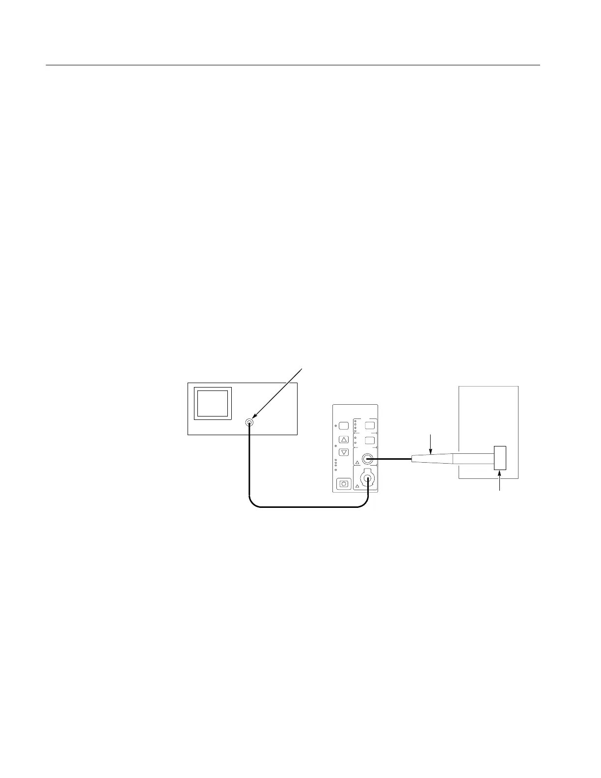
Figure 5--9 when making equipment connections.
Leveled
sine wave
generator
Output
50 Ω oscilloscope input -- use the TekProbe
InterfaceCableorusea50Ω cable. (Add
50 Ω termination here if oscilloscope has
only high-impedance input.)
Test oscilloscope
Current probe
HF current
loop
Figure 5- 9: Bandwidth test setup for TCP305 and TCP312
1. If you are using a Tektronix oscilloscope that supports the TekProbe Level 2
Interface, use the TekProbe Interface Cable to connect the amplifier
OUTPUT to the oscilloscope input. If you are not using a Tektronix
oscilloscope that supports the TekProbe Level 2 Interface, use a 50 Ω BNC
cable. If the input impedance of your oscilloscope is 1 MΩ, connect a 50 Ω
feedthrough termination at the oscilloscope input. Do not connect the
termination at the amplifier output.
2. Connect the current probe to the amplifier PROBE INPUT.
3. Connect the HF current loop to the output of the leveled sine wave generator.
Equipment C onnections
 Loading...

