Application Notes
TCPA300/400 Amplifiers and TCP300/400 Series Current Probes Instruction Manual
3-13
Inductance Measurements
You can use the TCPA300 and TCPA400 to measure inductance of coils. Two
different methods can be used: one for low-impedance pulse sources and another
for high-impedance pulse sources of known value.
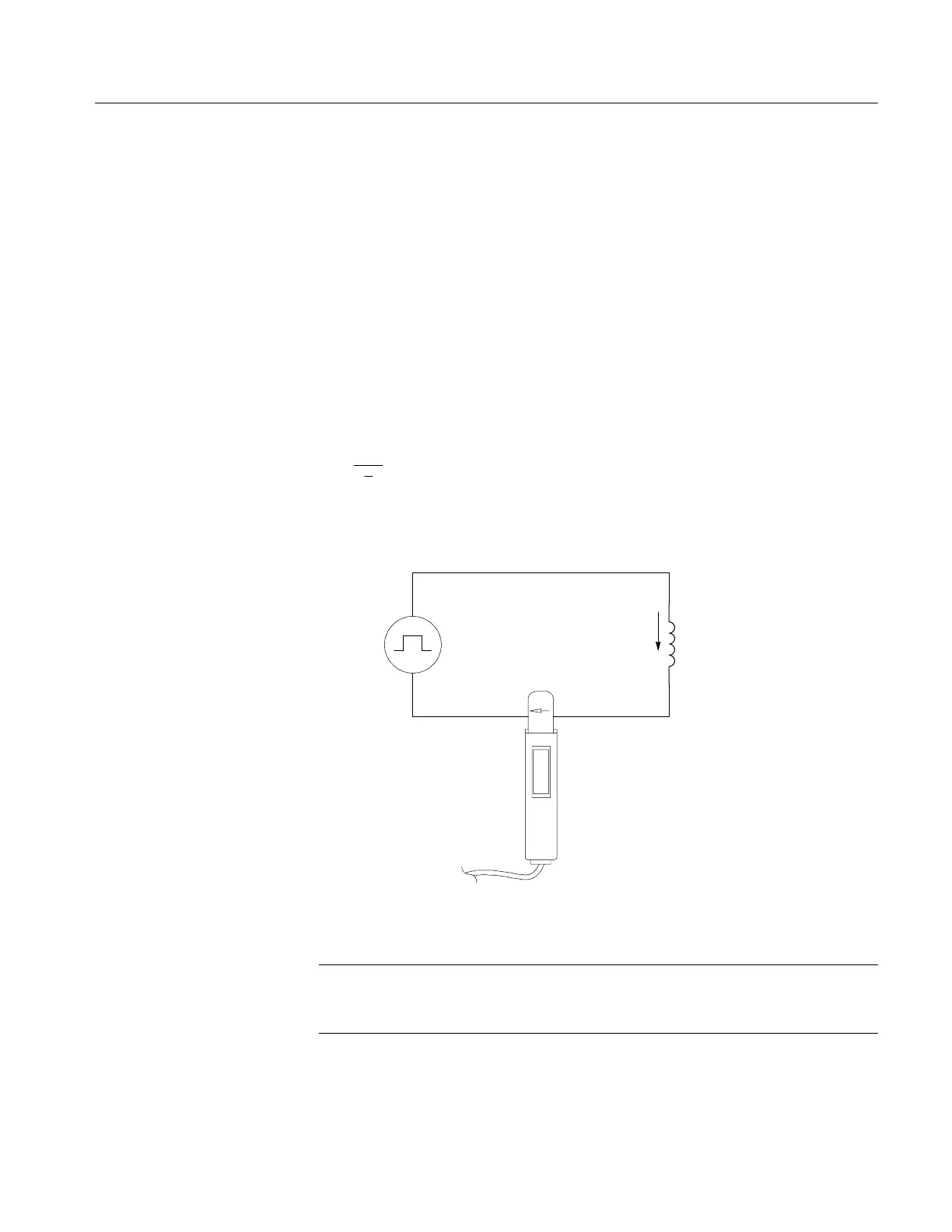
Figure 3--9 shows a measurement setup using a constant-voltage pulse generator
of extremely low output impedance. The inductor is connected across the output
terminals of the pulse source. The current probe is attached to one of the source
leads and the current ramp is measured.
The inductance is effectively defined by the slope of the current ramp, shown in
Figure 3--10, and is mathematically expressed by the following formula:
L =
− E
di
dt
where L is the inductance in henries, E is the voltage of the pulse generator, dt is
the change in time, and di is the change in current.
Pulse
generator
Inductor
Current
flow (i)
Current
probe
Figure 3- 9: Measuring inductance with a low-impedance source
NOTE. If the probe impedance is a significant part of the total circuit inductance,
measurement accuracy will be affected. Refer to the probe specifications for
probe insertion impedance.
Low-Impedance Pulse
Sources
 Loading...

