Troubleshooting
6–44
TDS 340A, TDS 360 & TDS 380 Technical Reference
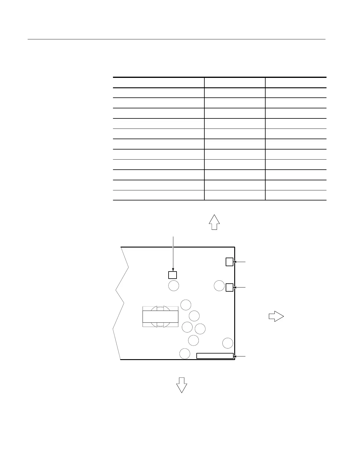
Table 6–4: Power supply secondary voltages
Location (see Figure 6–30) Minimum Maximum
J1 pin 2 +8.38 V +8.82 V
J1 pins 5 and 6 +4.87 V +5.13 V
J1 pin 8 +4.87 V +5.13 V
J1 pin 10 –8.38 V –8.82 V
J1 pin 11 –4.87 V –5.13 V
J1 pin 13, ON +0.991 V +1.137 V
J1 pin 13, STBY +1.272 V +1.406 V
J2 pin 1 +13.80 V +15.75 V
J3 pin 1, fan connected +10.20 V +13.80 V
J3 pin 1, fan disconnected +13.80 V +15.75 V
J4 pin 1 +13.80 V +15.75 V
J3 to fan
J2 to
monitor
J1 to main
board
Top of instrument
Front of
instrument
Bottom of instrument
J4 to option 14
(if used)
Figure 6–30: Power supply connector locations
 Loading...


