Removal and Replacement
6–6
TDS 340A, TDS 360 & TDS 380 Technical Reference
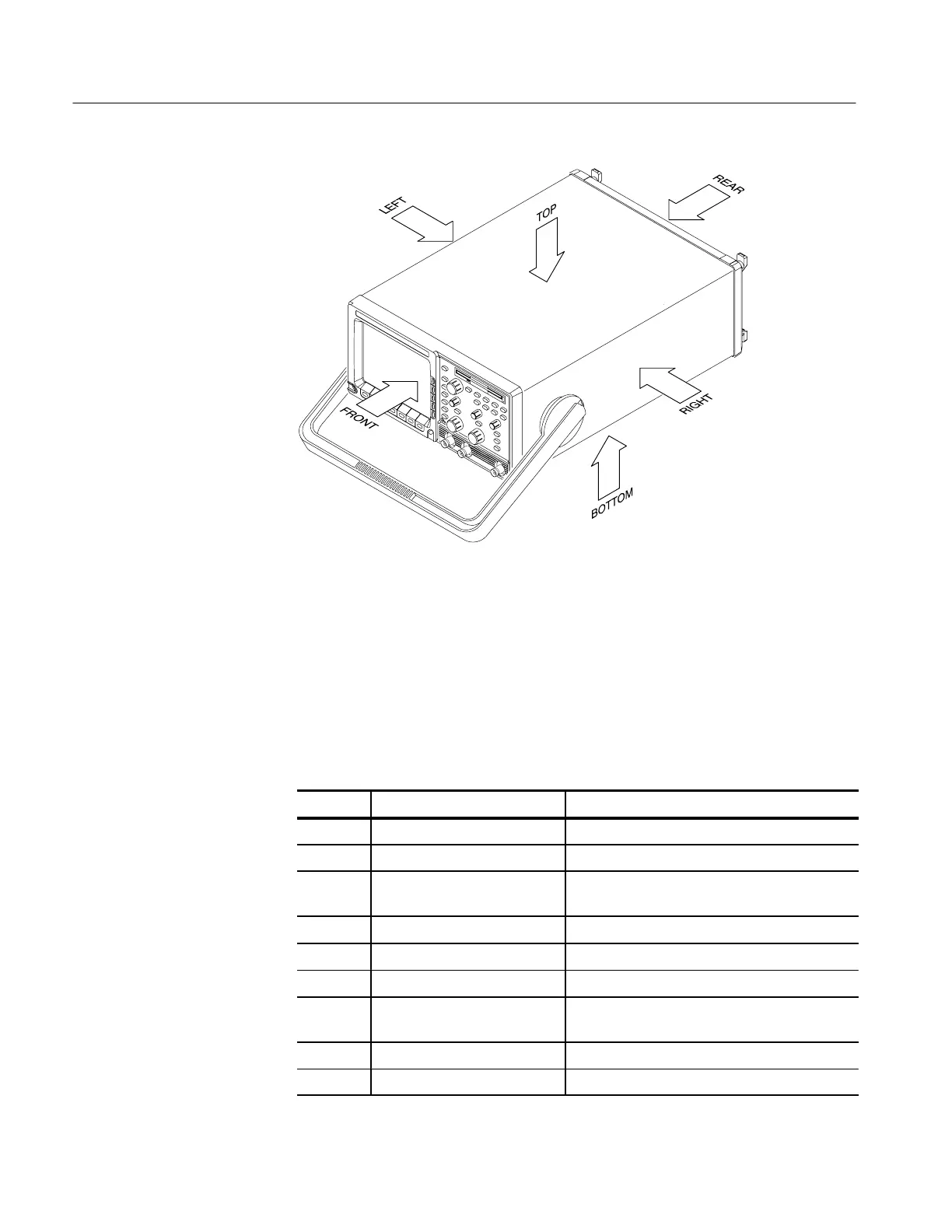
Figure 6–1: Oscilloscope orientation
The tools listed in Table 6–3 are required to completely disassemble the
oscilloscope into its modules. The tools required to remove an individual module
are listed before the first step of its procedure.
All the tools are standard tools readily available from tool suppliers.
Table 6–3: Tools required for module removal
Item no. Name Description
1 Screwdriver handle Accepts TorxR-driver bits
2 T-15 Torx tip TorxR-driver bit for T-15 size screw heads
3 T-20 Torx tip TorxR-driver bit for T-20 size screw heads. Used
only for removal of the cabinet handle
4 Flat-bladed screwdriver Screwdriver for removing standard-head screws
5 Pozidriv screwdriver Screwdriver for removing PozidrivR screws
6 Nut driver, 5/16 inch Used for removing earth ground cables
7 Nut driver, 3/16 inch Used for removing GPIB connector shell and
EMI gasket
8 Angle-tip tweezers Used for knob and shaft removal
9 Slip-Jaw Pliers Used for removing the front feet from the cabinet
Equipment Required
 Loading...


