Performance Tests
4–16
TDS 340A, TDS 360 & TDS 380 Technical Reference
14. When finished checking, set the horizontal SCALE back to the 10 ms/div
setting, and set the generator output frequency back to 50 kHz.
15. Press WAVEFORM OFF to remove Channel 1 from the display.
16. Press CH 2 and move the hookup to the CH 2 input.
17. Press TRIGGER MENU ! Source ! CH 2.
18. Repeat steps 6 through 13 for CH 2.
19. Disconnect the test hook up from the CH 2 input connector.
Time Base System Checks
This procedure checks those characteristics that relate to the Main and Delayed
time base system and are listed as checked under Warranted Characteristics in
the Specifications section.
Equipment Required: One time-marker generator (Item 9), one precision
coaxial cable, (Item 2) and one 50 W termination (Item 1).
Time Required: Approximately 5 minutes.
Prerequisites: See page 4–11.
Procedure:
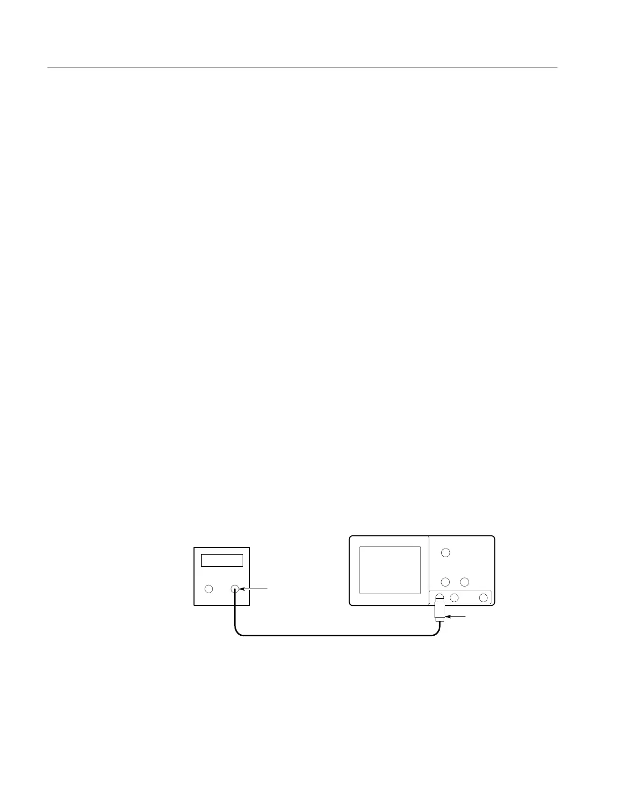
1. Connect, through a 50 W precision coaxial cable and a 50 W termination, the
time-mark output of a time-marker generator to CH 1, as shown in
Figure 4–8. Set the output of the generator for 10 ms markers.
Time mark
generator
Digitizing oscilloscope
50 W termination
Output
Figure 4–8: Hookup for sample rate check
Check Long-Term Sample
Rate and Delay Time
Accuracy
 Loading...


