Performance Tests
TDS 340A, TDS 360 & TDS 380 Technical Reference
4–13
11. Use the General Purpose Knob to set vertical offset to the setting listed in
Table 4–2 for the present vertical scale setting. The baseline level remains off
screen.
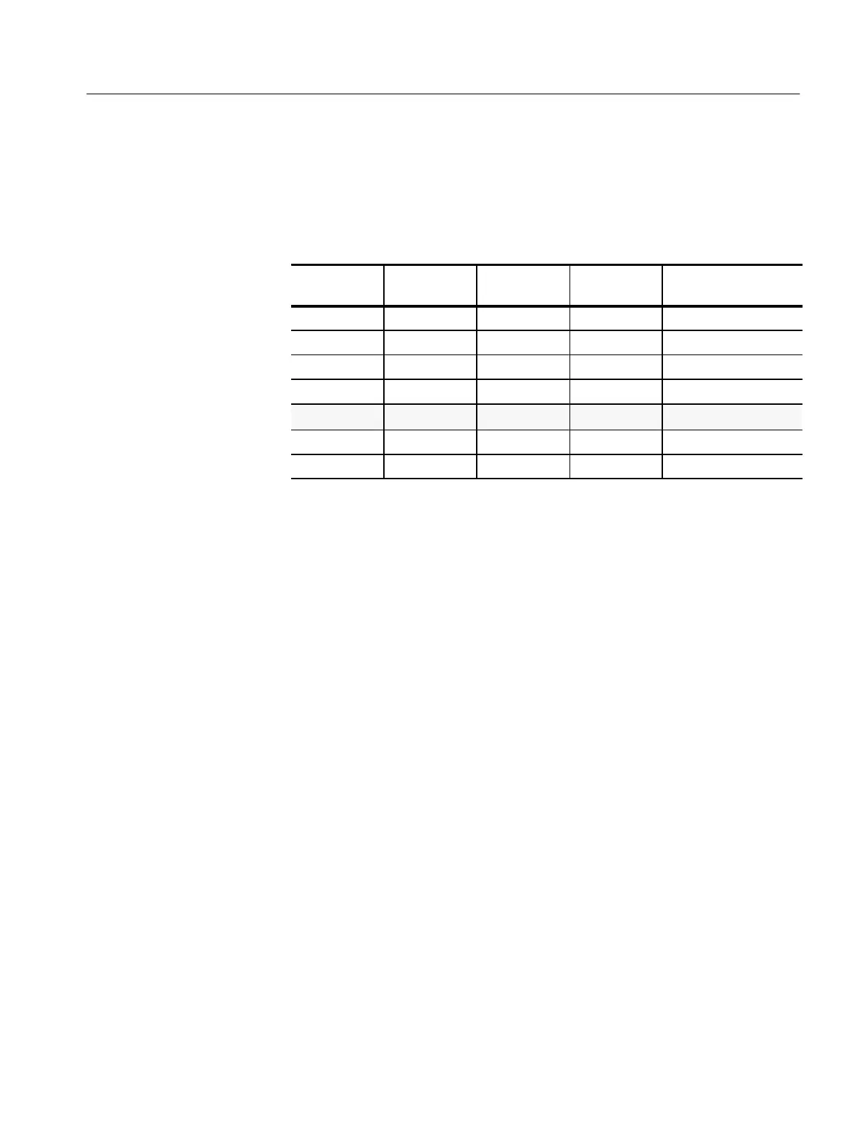
Table 4–2: DC accuracy
Vertical scale
setting
Position
setting (divs)
Offset setting
Generator
setting
Accuracy limits
1V +5 +100 V +98 V +97.1 V to +98.9 V
200 mV +5 +10 V +8.4 V +8.28 V to +8.52 V
50 mV –5 –1 V –0.6 V –581 mV to –619 mV
50 mV –5 –1 V –0.9 V –881 mV to –919 mV
n at 50 mV
+286 mV to +314 mV
10 mV –5 0 V +60 mV +54.6 mV to +65.4 mV
5mV 0 –1 V –990 mV –982 mV to –998 mV
12. Set the generator to the level and polarity indicated in Table 4–2 for the
vertical scale, position, and offset settings you have made. The DC test level
should appear on screen. (If it does not return, the DC accuracy check has
failed for the present vertical scale setting of the current channel.)
13. Check that the readout for the measurement Mean readout on screen is
within the limits listed for the present vertical scale and position/offset/gen-
erator settings.
14. Repeat steps 7 through 13 until you have checked all the vertical scale
settings listed in Table 4–2. Record the measurements for each of the 50 mV
settings.
15. Subtract the second 50 mV measurement from the first and compare the
result to the “D at 50 mV” limits in Table 4–2.
16. Press WAVEFORM OFF; then, press CH 2.
17. Set the generator output to 0 V.
18. Move the test hookup to the CH 2 input.
19. Repeat steps 5 through 15 for channel 2.
20. Set the generator output to 0 V.
21. Disconnect the cable at the CH 2 input connector.
 Loading...


