Specifications
1–2
TDS 340A, TDS 360 & TDS 380 Technical Reference
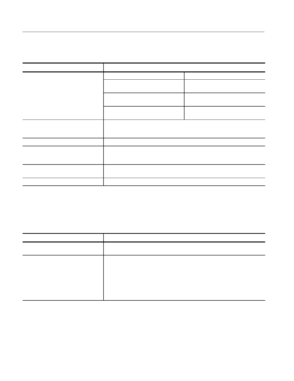
Table 1–1: Warranted characteristics — signal acquisition system (Cont.)
Name Description
ffs
t Volts/Div setting Offset accuracy
2 mV/div – 99.5 mV/div ±(0.4% × |Net Offset
1
|
+ 3 mV + 0.1 div × V/div setting)
100 mV/div – 995 mV/div ±(0.4% × |Net Offset
1
|
+ 30 mV + 0.1 div × V/div setting)
1 V/div – 10 V/div ±(0.4% × |Net Offset
1
|
+ 300 mV + 0.1 div × V/div setting)
Analog Bandwidth, DC Coupled TDS 340A: DC – ≥100 MHz
TDS 360: DC – ≥200 MHz; DC – ≥180 MHz for 2 mV/div
TDS 380: DC – ≥400 MHz; DC – ≥250 MHz for 2 mV/div
Cross Talk (Channel Isolation) ≥100:1 at 50 MHz with equal Volts/Div settings on each channel
Input Impedance, DC-Coupled TDS 340A: 1 MW ±1% in parallel with 20 pF ±2.0 pF
TDS 360: 1 MW ±1% in parallel with 20 pF ±2.0 pF
TDS 380: 1 MW ±1% in parallel with 12 pF ±2.0 pF
Input Voltage, Maximum ±300 V (DC or AC) CAT II; derate at 20 dB/decade above 100 kHz to 13 V peak AC at
3 MHz and above
Lower Frequency Limit, AC Coupled
2
≤10 Hz
1
Net Offset = Offset – (Position × Volts/Div). Net offset is the voltage level at the center of the A-D converter dynamic
range. Offset Accuracy is the accuracy of this voltage level.
2
The AC Coupled Lower Frequency Limits are reduced by a factor of 10 when 10X, passive probes are used.
Table 1–2: Warranted characteristics — time base system
Name Description
Accuracy, Long Term Sample Rate and
Delay Time
±100 ppm over any ≥1 ms interval
Accuracy, Delta Time Measurements
1,
2
For single-shot acquisitions using sample acquisition mode and a bandwidth limit setting
of FULL:
±(1 WI + 100 ppm × |Reading| + 0.6 ns)
For repetitive acquisitions using average acquisition mode with ≥16 averages and a
bandwidth limit setting of FULL:
±(1 WI + 100 ppm × |Reading| + 0.4 ns)
1
For input signals ≥5 divisions in amplitude and a slew rate of ≥2.0 divisions/ns at the delta time measurement points.
Signal must be acquired at a volts/division setting ≥5 mV/division.
2
The WI (waveform interval) is the time between the samples in the waveform record. Also, see the footnotes for Sample
Rate Range and Equivalent Time or Interpolated Waveform Rates in Table 1–11 on page 1–8.
 Loading...


