Jd751
______
_
~
945424-9701
SECTION
II
MAINTENANCE
2.1 GENERAL
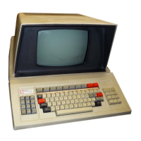
This section describes the maintenance philosophy for the Model 911 Video Display Terminal
and provides troubleshooting procedures to assist in fault isolation
to
the component level.
Component replacement procedures are given in the system depot maintenance manual for the
appropriate Model 990 series computer.
2.2 MAINTENANCE PHILOSOPHY
Depot maintenance for the Model 911 Video Display Terminal
is
based upon the use
of
a
diagnostic test executing in a
hot
mock-up system incorporating a Model 990 series computer, a
Model 990 Maintenance Unit, and a combination dual-trace oscilloscope/digital multimeter
as
shown in figures
2-1
and 2-2.
The Model 911 Video Display Terminal
is
tested using the 911 VDT diagnostic and its error
messages
to
troubleshoot the terminal. Component-level fault isolation
is
accomplished by using
the diagnostic
to
establish scoping loops through the portion
of
the terminal under test and
checking the logic with the aid
of
the logic diagrams in Model
990
Computer Family Mainte-
nance Drawings.
The keyboard subassembly
is
tested by connecting the keyboard
to
an
operable video display
unit and observing the code displayed by the row
of
LEDs on the rear
of
the video display unit
as
each keyboard key
is
struck. Faults are recorded and thus isolated
to
the replaceable
component by checking the faulty circuit from the cable connector at the video display unit
back through the cable and through
as
much
of
the keyboard assembly's circuitry
as
is
necessary
to
locate the fault.
The VDT controller and the power/logic board in the video display
unit
are tested by running
the diagnostic with the controller
or
video display unit installed in a
hot
mock-up system,
observing the error messages, and acting upon the indications given by the error messages.
Scoping loops are established by continuously repeating (looping) performance tests
that
give
error indications. The circuitry being exercised
is
then probed around the loop to isolate faulty
components or by executing diagnostic utility routines which exercise specific logic areas (e.g.,
CRU interface, cursor address register, memory read/write, etc.).
2.3 SPECIAL TEST EQUIPMENT
The special test equipment required to perform depot maintenance on the Model 911 Video
Display Terminal includes:
• Model 990 Computer
hot
mock-up system
•
911
VDT diagnostic, part number 2250101-1006 - Fully linked object for
990/10
-
Fully linked object for front panel.
Diagnostic medium (card, diskette, cassette) must be specified. Part number does not reflect
medium.
2-1
Digital Systems Division

 Loading...