~~--94_5_4_24_-9_1_0_1
____________________________________________
__
___,
I
L
185NS
,..-MIN,
I
CRUBIT
1 2
THRU
14
f!JlJ9
I
CRUBIT
1 5 •
MOD
SELA-
CRUB!TINT
t
STCRR1,2
(R
12=000016,R1=O20016)
t
TB
15
(R12a0000
16
,CRU
BIT
15=0)
L
185NS
~MIN,
1
r-~~~:
f¥'
///////ij' Ill///
I I I
11
t
(A)136256
NOTE:
SHADED
AREAS
SIGNIFY
THAT
SIGNALS
CAN
EITHER
BE
HIGH
OR
LOW
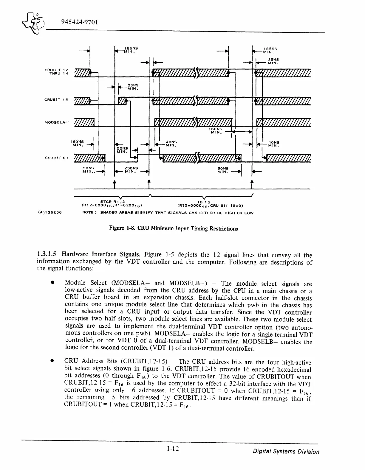
Figure
1-8.
CRU Minimum Input Timing Restrictions
1.3.1.5 Hardware Interface Signals. Figure
1-5
depicts the 12 signal lines
that
convey all the
information exchanged
by
the VDT controller and the computer. Following are descriptions
of
the signal functions:
• Module Select
(MODSELA-
and MODSELB-) - The module select signals are
low-active signals decoded from the CRU address
by
the CPU in a main chassis
or
a
CRU buffer board in an expansion chassis. Each half-slot connector in the chassis
contains one unique module select line
that
determines which pwb in the chassis has
been selected for a CRU
input
or
output
data transfer. Since the VDT controller
occupies two
half
slots, two module select lines are available. These
two
module select
signals are used
to
implement the dual-terminal VDT controller option
(two
autono-
mous controllers
on
one pwb).
MODSELA-
enables the logic for a single-terminal VDT
controller,
or
for VDT 0
of
a dual-terminal VDT controller.
MODSELB-
enables the
iogic for the second controiier (VDT
i)
of
a duai-terminai controiier.
• CRU Address Bits (CRUBIT,12-15) - The CRU address bits are the four high-active
bit select signals shown in figure 1-6. CR UBIT, 12-15 provide
16
encoded hexadecimal
bit addresses (0 through F
16
) to the VDT controller. The value
of
CRUBITOUT when
CRUBIT, 12-15 = F
16
is
used by the computer
to
effect a 32-bit interface with the VDT
controller using only 16 addresses.
If
CRUBITOUT = 0 when CRUBIT,12-15 = F
16
,
the remaining
15
bits addressed by CRUBIT, 12-15 have different meanings than
if
CRUBITOUT= 1 when CRUBIT,12-15 = F
16
.
1-12
Digitai
Systems Division

 Loading...
