~~-~~~~~~~~-
~
945424-9701
SECTION I
THEORY
OF
OPERATION
1.1 GENERAL
This manual provides depot-level operation and maintenance information for the United States,
European, and Japanese versions
of
the
Texas Instruments Model 911 Video Display Terminal
used with the Model 990 family
of
computers.
This section provides a discussion
of
the
operation
of
the Model 911 Video Display Terminal.
Functional theory
is
described, supported
by
block diagrams, circuit diagrams, flowcharts and
timing diagrams. Detailed discussions
of
the
terminal's ·circuitry and descriptions
of
the interfaces
within the terminal and between the terminal and its host
computer
are also provided.
1.2 SYSTEM DESCRIPTION
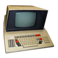
The Model 911 Video Display Terminal consists
of
the following functional entities:
• Keyboard with associated electronics
• Keyboard and video data paths in display unit assembly
• Power supply
• CRT
monitor
• Video display terminal (VDT) controller
The keyboard and keyboard electronics are contained in the keyboard assembly housing. The
keyboard and video data paths in the display unit assembly, power supply, and CRT
monitor
are
contained in the display unit cabinet. The VDT controller
is
in the main
computer
chassis
or
an
expansion chassis and interfaces with the computer's Communications Register Unit (CRU). The
display unit and the VDT controller are interconnected
by
an interface cable.
Figure
1-1
shows the components
of
a basic Model 911 VDT kit, and figure
1-2
is
a block diagram
of
the terminal. Figure
1-3
shows the locations
of
the components located in the display unit
cabinet. The following paragraphs describe each component
of
the terminal and function(s)
of
each
component within the terminal subsystem.
1.2.1 KEYBOARD. The keyboard consists
of
keyswitch arrays on a printed wiring board (pwb) in
the keyboard's own housing. The etched circuitry on the pwb forms an electrical contact matrix
for the keyswitches. The keyboard also contains logic
that
performs the following functions:
• Detects key depression (switch closure).
• Allows multilevel encoding
of
data keys using the following mode keys: SHIFT,
CONTROL, and UPPER CASE LOCK. The Japanese keyboard has two additional keys
for alphanumeric
or
Katakana mode select.
• Produces an eight-bit code for each data key actuation.
1-1
Digital
Systems Division

 Loading...