~-------
~
945424-9701
2.3.i
HOT MOCK-UP SYSTEM. Operating instructions for
the
hot
mock-up system are pro-
vided in
the
system
depot
maintenance manual for
the
appropriate Model
990
series
computer.
NOTE
Refer
the the
manufacturer-supplied user manuals for oscilloscope/
digital
multimeter
operating procedures.
2.3.2
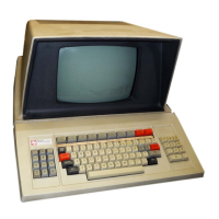
DIAGNOSTIC. The 911 VDT diagnostic executes
under
control
of
the
VERBPAC
to
test
and
facilitate fault diagnosis within a Model 911 Video Display Terminal consisting
of
a
keyboard, a VDT controller, a video display
unit
and interconnecting cables.
If
a VDT controller
pwb
contains logic
for
two
controllers,
the
board
responds
to
two
CRU
base addresses. The
diagnostic
must
be
executed
for each controller using
the
appropriate
CRU
base address for each
execution.
An
error
counter
records
detected
failures. Accumulated errors are
printed
upon
conclusion
of
each routine. When
loop
routines
(LI,
L2, L3, etc.) are executed,
the
accumulated
count
is
printed
after
each pass through a test part.
If
error
messages are suppressed,
error
counts may be
observed
by
aborting
the
current
test (depress
"@"
on
the
keyboard
of
the
interactive device)
and
using
the
Print
Error
Count
(PE) verb.
2.3.2.1 Loading
the
Diagnostic. Following are procedures for loading
the
911 VDT diagnostic
into
a
hot
mock-up system from a Model 733
ASR
Data
Terminal.
1.
Apply
power
to
hot
mock-up system.
2. Insert cassette containing 911 VDT diagnostic
(part
number
2250101-1006)
into
~odel
733
ASR
Data Terminal cassette transport. Set 733 POWER switch
to
ON.
3. Set 733 CONT START/STOP switch
to
STOP.
4. Press 733 REWIND switch for appropriate cassette transport.
5. Set 733 KEYBOARD, PLAYBACK and
PRINTER
switches
to
LINE.
6. Set 733
OFF
LINE/ON LINE switch
to
ON LINE.
7. Press 733
LOAD/FF
and wait for READY indicator.
8. Set programmer panel key switch
to
UNLOCK.
9. Press programmer panel LOAD switch.
2.3.2.2
Using
the
Diagnostic. There are two versions
of
the
performance
demonstration
test:
one
is for
the
Japanese model;
the
other
is
for
the
United States and European models. Consult
the
operating instructions
for
procedures involving
operator
interaction
during diagnostic testing.
Detailed
information
about
the
scope
of
each
test
is provided in
the
program description.
United States and European
Program description - 911 VDT diagnostic
part
number
2250101-9901
Operating instructions - 911 VDT diagnostic
part
number
2250101-9920
Japanese Katakana
Program description - 911 VDT diagnostic
part
number
2250253-9901
Operating instructions -- 911 VDT diagnostic
part
number
2250253-9920
2-4
Digital
Systems
Division

 Loading...