~-------
~
945424-9701
2.6.1
POWER/LOGIC
PWB
PRELIMINARY
CHECKOUT.
Upon receipt
of
a suspect power/
logic pwb from the field maintenance facility, visually inspect the board for the problems listed
in paragraph 2.4.1.
If
a thorough visual inspection indicates no problems, proceed with the fault
isolation procedure for the pwb.
2.6.2
POWER/LOGIC
PWB
FAULT
ISOLATION
PROCEDURES.
Table
2-2
lists procedures for
troubleshooting the power/logic pwb with a
hot
mock-up system. Table
2-3
lists procedures
to
isolate faults indicated by abnormal conditions detected by table
2-2
procedures.
2.7
VDT
CONTROLLER
MAINTENANCE
PROCEDURES
Maintenance procedures for the VDT controller consist
of
a preliminary checkout
to
determine
if
any problems exist which might be visually detected, and fault isolation procedures to locate
faulty circuit components.
Step
2
3
4
Table
2-2.
Power/Logic
PWB
Troubleshooting
Procedure
Procedure
Install power/logic pwb
into
hot
mock-up system.
Apply power
to
hot
mock-up
system.
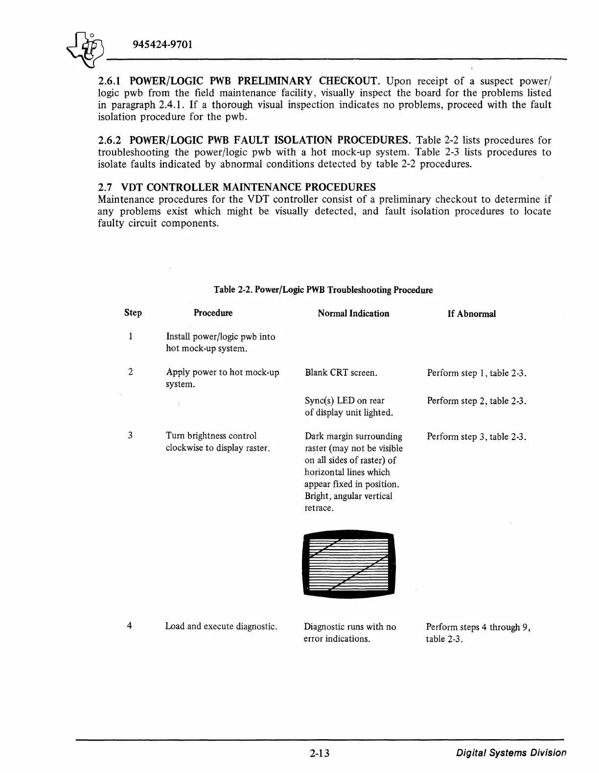
Turn brightness control
clockwise
to
display raster.
Load and execute diagnostic.
Normal
Indication
Blank CRT screen.
Sync(s) LED
on
rear
of
display
unit
lighted.
Dark margin surrounding
raster (may
not
be visible
on all sides
of
raster)
of
horizontal lines which
appear fixed in position.
Bright, angular vertical
retrace.
Diagnostic runs with
no
error indications.
2-13
If
Abnormal
Perform step 1, table 2-3.
Perform step
2,
table 2-3.
Perform step
3,
table 2-3.
Perform steps 4 through
9,
table 2-3.
Digital
Systems
Division

 Loading...
