~,--,~
945424-9701
~-------
2.4 GENERAL MAiNTENANCE PROCEDURES
Maintenance procedures consist
of
a preliminary checkout
of
the
suspect unit
to
determine
if
any problems exist which might be visually
detected
and fault isolation procedures
to
locate
faulty circuit components. The following paragraphs describe those procedures
as
they
apply
generally
to
the
components
of
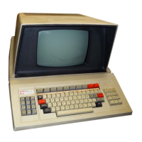
the Model 911 Video Display Terminal. More detailed procedures
for specific components are included with the discussions
of
maintenance procedures for
the
~~~-~-~-+~
~Ulll
jJUllc;ll
l~.
2.4.1
PWB
PRELIMINARY CHECKOUT. Upon receipt
of
a suspect pwb from
the
field main-
tenance facility, visually inspect
the
board
for
the
following:
•
Broken board
•
Loose
or
missing components
•
Damaged (broken) components, wires,
etc
.
•
Broken
or
missing heat sinks
•
Broken, missing,
or
disconnected
jumper
wires
•
•
Foreign materials lodged between package pins
that
may
be causing
short
circuits .
If
a thorough visual inspection indicates
no
problems, proceed with
the
fault isolation procedures
for
the
pw~.
2.4.2 GENERAL FAULT ISOLATION PROCEDURES. Each
component
of
the
Model 911
Video Display Terminal
is
tested individually
by
incorporating
the
suspect
component
into
the
hot
mock-up system shown in figure
2~
I
or
2~2.
All components
of
the system, except the unit
to
be tested, should be verified
to
be operable. The 911 VDT diagnostic
is
loaded and executed in
accordance with
the
instructions in the Model 990 Computer Diagnostics Handbook,
part
number
945400-9701. The diagnostic
is
used, with
the
special verbs available,
to
establish scoping loops
for the unit
under
test.
2.4.2.1 Scoping Loops. A scoping loop
is
a short repetitive software program which establishes
and maintains a set
of
conditions in the circuitry under observation so
that
an error
of
normally
brief duration can be observed and isolated. Once an error message has been printed, determine
which test was being performed from
the
printout
of
the 733
or
the
CRT
screen. Failure
of
diagnostic test
part
El,
E2,
or
E3 may be looped
by
activating the
LI,
L2,
or
L3 verb, respectively.
2.5 KEYBOARD MAINTENANCE PROCEDURES
Keyboard maintenance procedures consist
of
a preliminary checkout
to
determine
if
any
problems exist which might be visually detected, and fault isolation procedures to locate faulty
circuit components. The following paragraphs describe those procedures.
2.5
.1
KEYBOARD PRELIMINARY CHECKOUT. Upon receipt
of
a suspect keyboard from the
field maintenance facility, visually inspect
the
assembly for any indications
of
damage from
dropping
or
mishandling. Note any indications for future reference. Perform the following
procedure
to
check
out
the
keyboard prior
to
troubleshooting.
1.
Turn keyboard assembly upside down and remove four screws.
2. Grasp keyboard assembly at
both
ends
to
keep cover
top
and
bottom
from separating
and
tum
assembiy upright.
2-8
Digital
Systems Division

 Loading...