~-------
~
945424-9701
1.3.4.2 Beep Enable (BET,1,2,T). Beep Enable are complementary
outputs
of
a differential line
driver
on
the
VDT controller
that
are active for 0.3 seconds (nominal) in response
to
Beep Enable
(CR U
output
bit E
16
with
output
bit F
16
= 1
).
The Beep Enable pair enable an oscillator
on
the
power/logic pwb for their duration
to
produce an audible
tone
via a loudspeaker in
the
base
of
the
display unit housing.
i .3.4.3 Modem Audio (MODIN). Modem Audio carries low-level audio signals from the modern
connected
to
the
modem audio
jack
on
the
VDT controller. Modem Audio allows audio signals
from a
modem
to
be amplified and sent
to
the
loudspeaker in
the
display unit housing. A patch
cord
(part
number
09963
73-1)
is
needed
to
connect
the
modem
to
the
controller. A discrete
jumper
must
also be made
on
the
power
supply /logic pwb between
connector
J2 pin 9 and resistor
R34.
If
the
modem audio
is
enabled, this signal line in
the
interconnection cable
must
be
kept
short
to
prevent noise pickup in
the
alarm circuits. The
modem
signal line should be less
than
15.24 metres (50 feet).
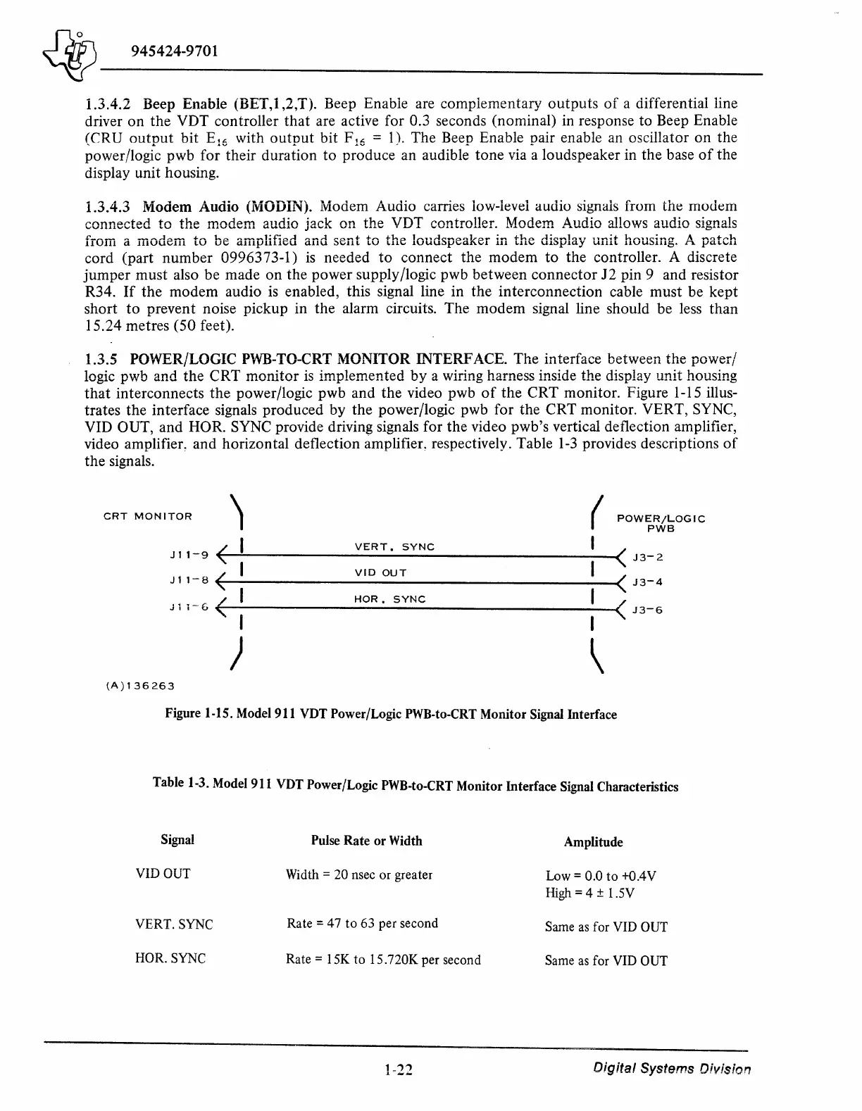
1.3.S POWER/LOGIC PWB-TO-CRT MONITOR INTERFACE. The interface between
the
power/
logic pwb and
the
CRT
monitor
is
implemented
by
a wiring harness inside the display unit housing
that
interconnects
the
power/logic pwb and
the
video pwb
of
the
CRT
monitor. Figure 1-15 illus-
trates the interface signals produced by
the
power/logic pwb for the
CRT
monitor. VERT, SYNC,
YID OUT, and HOR. SYNC provide driving signals for
the
video pwb's vertical deflection amplifier,
video
amplifier~
and horizontal deflection amplifier, respectively. Table
1-3
provides descriptions
of
the
signals.
CRT
MONITOR
l
(
POWER/LOGIC
PWB
<
I
VERT.
SYNC
<
J3-2
J
11-9
J11-B
(
I
VID
OUT
<
J3-4
I
/
HOR.
SYNC
/
J 1
1~6
J3-6
I
I
)
\
(A)136263
Figure 1-15.
Model
911
VDT
Power/Logic
PWB-to-CRT
Monitor Signal Interface
Table
1-3.
Model
911
VDT
Power/Logic
PWB-to-CRT
Monitor Interface
Signal
Characteristics
Signal
Pulse
Rate or
Width
Amplitude
VIDOUT
Width = 20 nsec or greater
Low=
0.0
to
+0.4V
High
= 4 ± 1.SV
VERT. SYNC
Rate = 4 7
to
63 per second
Same
as
for VID OUT
HOR. SYNC
Rate=
I
SK
to 15.720K per second
Same
as
for VID OUT
1-22
Digital
Systems Division

 Loading...
