~
945424-9701
~
/..,0
0
0
2
3
4
5 6
7 8
9
to
C
r
-,--T--r--,--,--,--T--r-n
I
LSB
I I I I I I I
MSB
IPARITYI
STOP
__
...J
__
i_
__
L_...J
__
J
__
J
__
i__-L_...J
A)136261
Figure
1-13.
Model
911
VDT
Power/Logic
PWB-to-VDT
Controller Data Format
DISPLAY
UNIT
HOUS
l~JG
INTERCONNECTION
CABLE
POWER/LOGIC
\
PWB
J
(
GND
<
J4-1
J2-1
,t
JS-1
J2-2
(
I \
CVID/VIV
<
J4-2
JS-2
'
.....
'
<
BET1T
<
J4-7
J2-7
VOTO
JS-7
JZ-8
(
BET2T
<
J4-8
JS-8
<
I
MODIN
(
J4-9
J2-9
JS-9
I
)
)
\
VDT1
(A)136262
Figure
1-14.
Model
911
VDT
Controller-to-Power/Logic
PWB
Interface
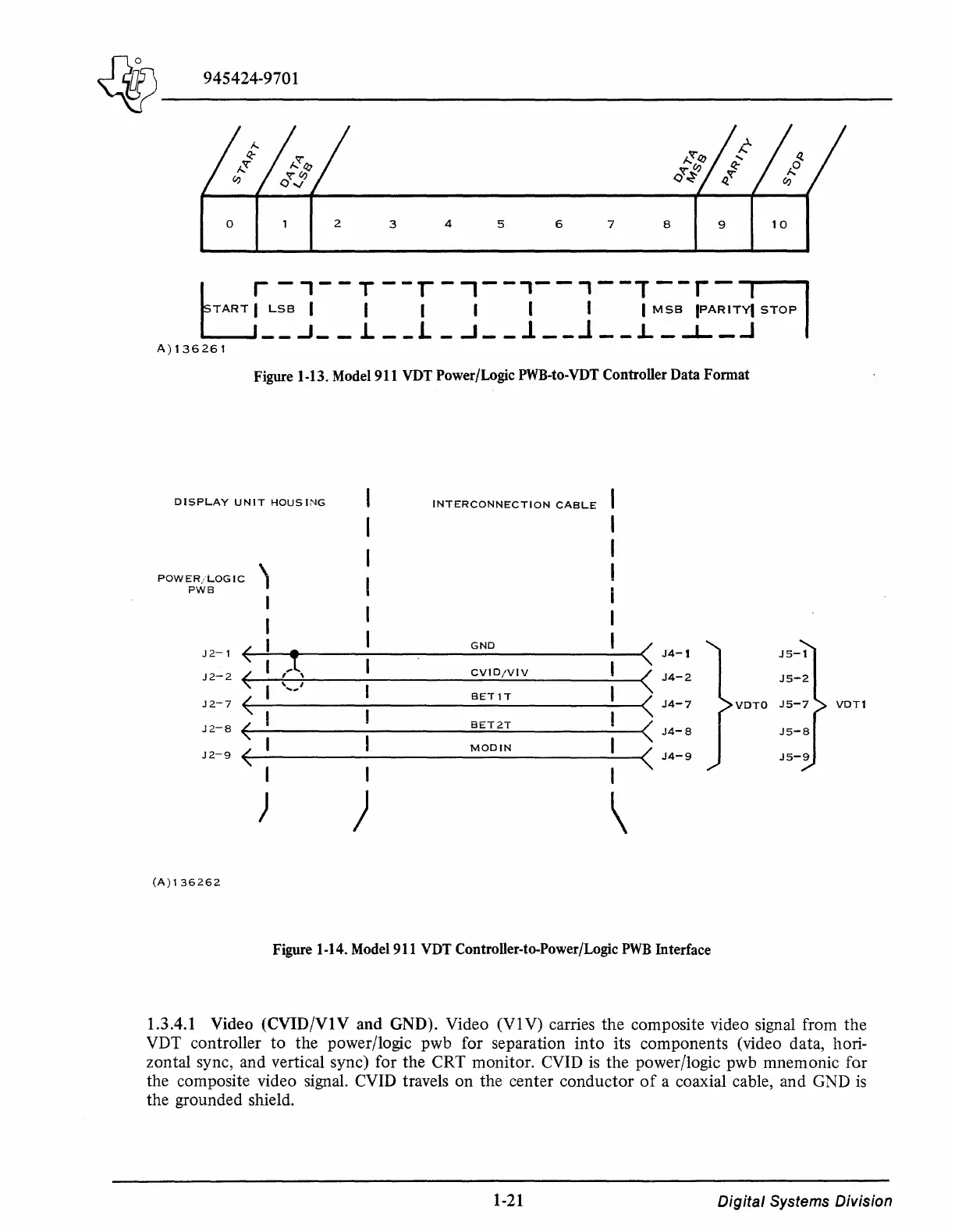
1.3.4.1 Video (CVID/VlV and GND). Video
(VlV)
carries the composite video signal from the
VDT controller to the power/logic pwb for separation into its components (video data, hori-
zontal sync, and vertical sync) for the CRT monitor. CVID
is
the power/logic pwb mnemonic for
the composite video signal. CVID travels on the center conductor
of
a coaxial cable, and GND
is
the grounded shield.
1-21
Digital
Systems Division

 Loading...
