N
I
N
........
0
<9:
-
Q)
-
(/)
~
-
<b
3
en
0
~-
c;;·
er
::s
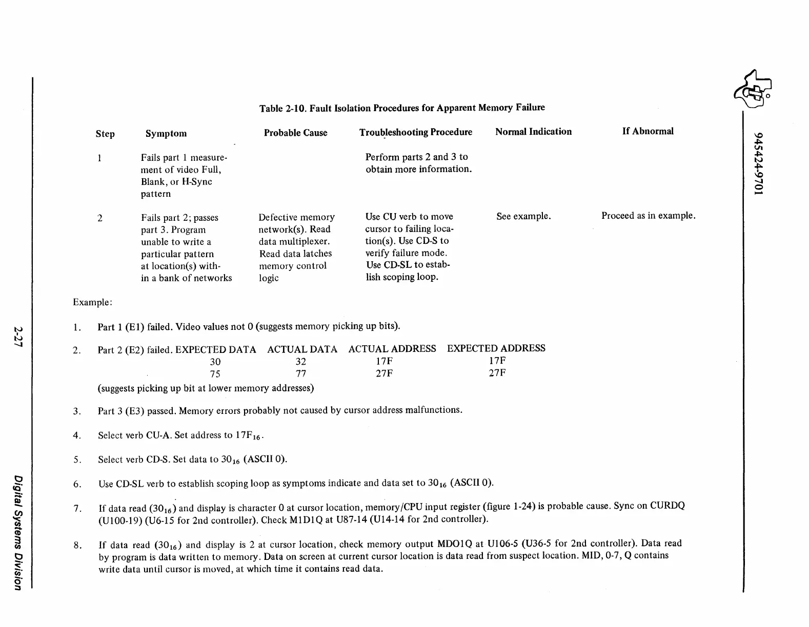
Step
2
Symptom
Fails part 1 measure-
ment
of
video Full,
Blank,
or
H-Sync
pattern
Fails part 2; passes
part 3. Program
unable
to
write a
particular
pattern
at
location(s) with-
in a
bank
of
networks
Table 2-10.
Fault
:Isolation Procedures for
Apparent
Memory Failure
Probable Cause
Defective
memory
network(s). Read
data multiplexer.
Read data latches
memory control
logic
Trou~leshooting
Procedure
Perform parts 2
and
3
to
obtain
more information.
Use
CU verb
to
move
cursor
to
failing loca-
tion(
s).
Use
CD-S
to
verify failure mode.
Use CD-SL
to
estab-
lish scoping loop.
Normal Indication
See example.
If
Abnormal
Proceed
as
in example.
Example:
1.
2.
3.
4.
5.
6.
7.
8.
Part 1
(El)
failed. Video values
not
0 (suggests memory picking up bits).
Part 2 (E2) failed. EXPECTED DATA ACTUAL DATA ACTUAL ADDRESS
30
32
17F
75 77
27F
(suggests picking
up
bit
at lower
memory
addresses)
EXPECTED ADDRESS
17F
27F
Part 3 (E3) passed. Memory errors probably
not
caused
by
cursor address malfunctions.
Select verb CU-A. Set address
to
17F
16
.
Select verb CD-S. Set
data
to
30
16
(ASCII 0).
Use
CD-SL verb
to
establish scoping
loop
as
symptoms indicate and data set
to
301
6
(ASCII
O).
If
data read
(30
16
) and display
is
character 0 at cursor location, memory/CPU
input
register (figure 1-24) is probable cause. Sync on CURDQ
(Ul00-19)
(U6-15 for
2nd
controller). Check
MlDlQ
at U87-14 (U14-14 for
2nd
controller).
If
data read
(30
16
) and display
is
2 at cursor location, check memory
output
MDOlQ
at
Ul06-S (U36-5 for
2nd
controller). Data read
by program
is
data written
to
memory. Data
on
screen
at
current cursor location is data read from suspect location. MID, 0-7, Q contains
write data until cursor
is
moved,
at
which time
it
contains read data.
 Loading...

