www.ti.com
ADS1298ECG-FE/ADS1198ECG-FE Hardware Details
35
SBAU171D–May 2010–Revised January 2016
Submit Documentation Feedback
Copyright © 2010–2016, Texas Instruments Incorporated
ADS1298ECG-FE/ADS1198ECG-FE
5 ADS1298ECG-FE/ADS1198ECG-FE Hardware Details
The ADS1298 ECG front-end evaluation board is configured to be used with the TI MMB0 data converter
evaluation platform. The ADS1298ECG-FE board is a four-layer circuit board. The board schematic and
layout are provided in Appendix A.
The ADS1298ECG-FE can be used as a demonstration board for standard, 12-lead ECG applications with
an input configuration of 10 electrodes. Users can also bypass the 12-lead configuration and provide any
type of signal directly to the ADS1298 through a variety of hardware jumper settings (JP26-33; see
Section A.4). External support circuits are provided for testing purposes such as external references,
clocks, lead-off resistors, and shield drive amplifiers.
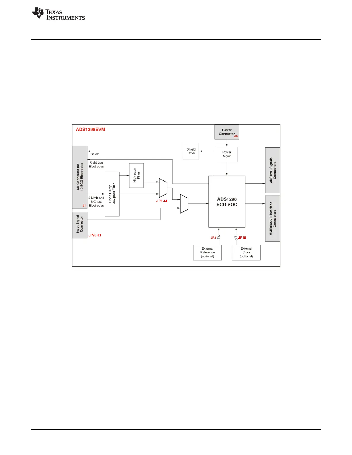
Figure 36 shows the functional block diagram with important jumper names for the board.
Figure 36. ADS1298ECG-FE Front-End Block Diagram

 Loading...


