ADS1298ECG-FE/ADS1198ECG-FE Hardware Details
www.ti.com
36
SBAU171D–May 2010–Revised January 2016
Submit Documentation Feedback
Copyright © 2010–2016, Texas Instruments Incorporated
ADS1298ECG-FE/ADS1198ECG-FE
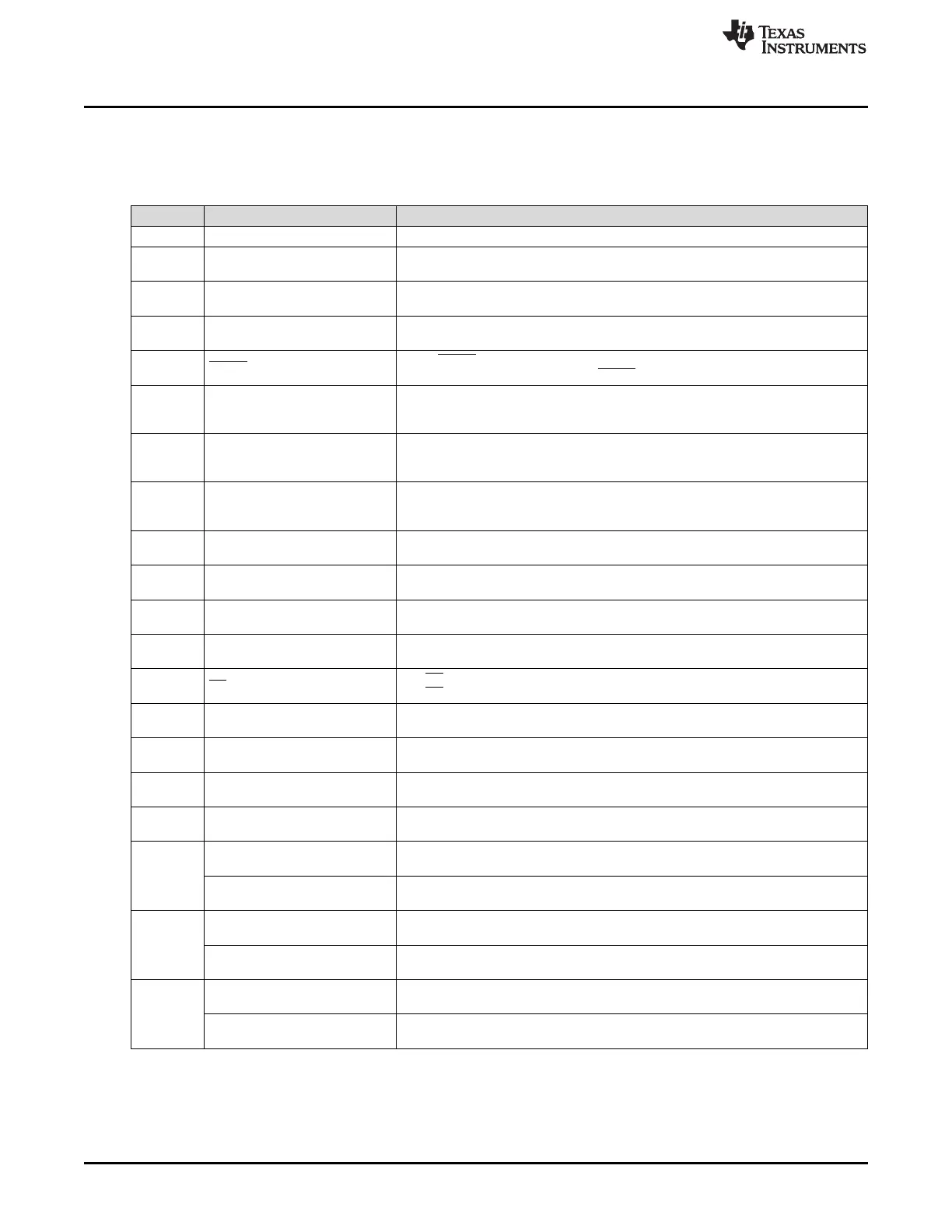
5.1 Jumper Description
Table 5 shows the jumpers on the ADS1298ECG-FE and options available for each jumper.
(1)
Requires installation of JP25 and references U3/U4
(2)
Requires installation of U2
(3)
Requires installation of JP3 and references U3/U4
Table 5. ADS1x98ECG-FE Default Jumper/Switch Configuration
Jumper Function Settings
JP1 Installed RLD feedback
JP2 AVDD supply source
1-2: AVDD selected for bipolar supply operation (AVDD = +2.5V)
2-3: AVDD selected for single supply operation (AVDD = +3.0V)
JP3
External Reference Connection
(Header Not Installed)
(1)
Open: External reference not connected
Installed: External reference connected
JP4
Connect EVM +5V rail to
J4(power header)
Open: EVM +5V must be supplied externally
Installed: EVM +5V supplied from J4 (power header)
JP5 PWDN source
Open: PWDN pin controlled from J5 header (pulled up to DVDD)
Installed: Device is powered down (PWDN pin = AGND)
JP6 to
JP114
Input signal DC/AC couples
(Header Not Installed)
1-2: DC-coupled input signals (Pins 1-2 shorted on PCB)
2-3: AC-coupled input signals (Requires installation of header and cutting PCB
short of pin 1-2)
JP15 ECG shield drive connected
1-2: ECG shield is grounded (AGND)
2-3: ECG shield is connected to buffer (required U2 installation, otherwise shield
connection is open)
JP16
Wilson Central Terminal (WCT)
connection
Open: WCT NOT connected to JP26-30 and JP33
Installed: WCT connected to JP26-30 and JP33 for connection to CH1 and CH4-8
IN-
JP17
ECG shield drive buffer
input(Header Not Installed)
(2)
1-2: ECG shield drive connected to RLDOUT
2-3: ECG shield drive connected to RLDINV
JP18 CLK connection
1-2: CLK connected to DSP (J3.17)
2-3: CLK connected to OSC1
JP19 OSC1 Enable
1-2: OSC1 enabled
2-3: OSC1 disabled
JP20 AVSS supply source
1-2: AVSS selected for single supply operation (AVSS = 0V (AGND))
2-3: AVSS selected for bipolar supply operation (AVSS = -2.5V)
JP21 CS source
1-2: CS connected to DSP via J3.1
2-3: CS connected to DSP via J3.7
JP22 START source
1-2: START comes from J3.1
2-3: START comes from J3.14
JP23 CLKSEL source
1-2: External Master Clock
2-3: Internal Master Clock (CLKSEL controlled by J3.2 (pulled up to DVDD))
JP24 DVDD Supply Select
1-2: DVDD supply = 1.8V
2-3: DVDD supply = 3.3V
JP25
External Reference Selection
(Header Not Installed)
(3)
1-2: Select U4 as reference source
2-3: Selected U3 as reference source
JP26
CH8- connection
Open: Channel input not connected
Installed: Channel input connected to WCT (requires JP16 to be installed)
CH8+ connection
Open: Channel input not connected
Installed: Channel input connected to ECG_V1
JP27
CH7- connection
Open: Channel input not connected
Installed:Channel input connected to WCT (requires JP16 to be installed)
CH7+ connection
Open: Channel input not connected
Installed: Channel input connected to ECG_V5
JP28
CH6- connection
Open: Channel input not connected
Installed: Channel input connected to WCT (requires JP16 to be installed)
CH6+ connection
Open: Channel input not connected
Installed: Channel input connected to ECG_V4

 Loading...


