Printed Circuit Board Layout
www.ti.com
44
SBAU171D–May 2010–Revised January 2016
Submit Documentation Feedback
Copyright © 2010–2016, Texas Instruments Incorporated
Schematics, BOM, Layout, and ECG Cable Details
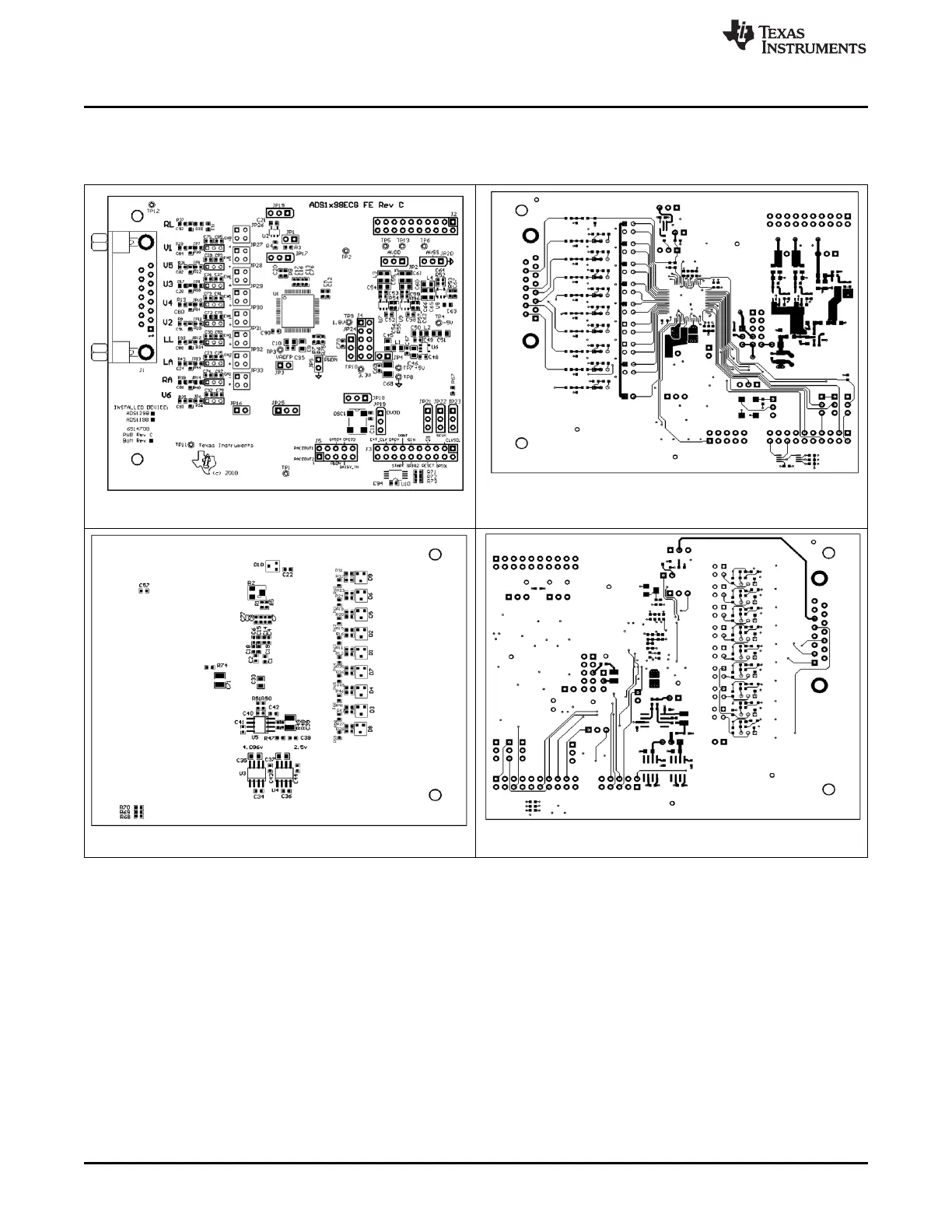
A.4 Printed Circuit Board Layout
Figure 38 through Figure 43 show the ADS1x98ECG-FE PCB layouts.
Figure 38. Top Component Placement
Figure 39. Top Layer
Figure 40. Bottom Component Placement
Figure 41. Bottom Layer

 Loading...


