35
SME2-IS - Manual - 06- 2021
FUNCTIONAL CHARACTERISTICS
— Ground directional overcurrent - 67N
Foreword
The function detects ground faults on both isolated neutral and compensated neutral grids, without
the need to modify its conguration when switching between the two types of grid.
The algorithm is based on a numerical analysis of the signals (DFT) using fast sampling and a phase
locked loop algorithm (PLL); this measures the signals integrally even in the presence of large vari-
ations of frequency.
The fault signal (TS67AV) is supplied to the remote control unit via the closing of a contact connected
to terminal 5 of the MB terminal block and to the communications interfaces.
The calibration uses an adjustable homopolar voltage threshold
[1]
U0> and a residual current
threshold
[2]
IED>.
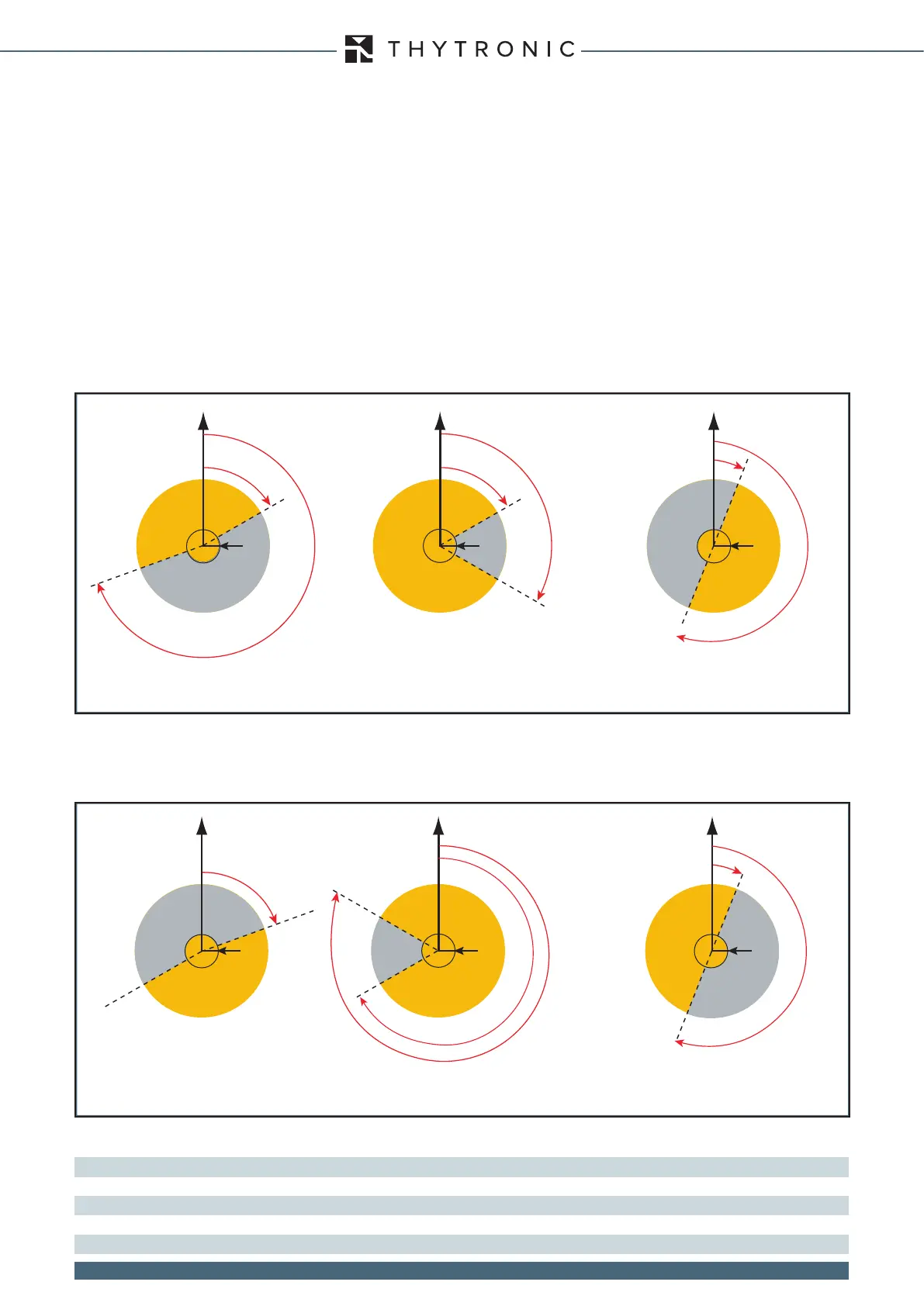
The directional function detects the ground fault if the following conditions hold:
- homopolar voltage greater than threshold U0>,
- residual current greater than threshold IED>,
- phase shift of the residual current relative to the homopolar voltage within the set tripping threshold
(I0 angle delayed relative to U0 in the clockwise direction and no inversion),
- all the above conditions hold for a time greater than 80 ms.
The functions has four adjustable thresholds with time-independent programmable tripping times;
each of the protection thresholds can be disabled or enabled separately.
[3]
An external remote control system signal can be used to invert the reference direction in case of
power supply to the grid from the opposite side (tripping directionality on the secondary substation
bar side); the inversion signal is supplied by the remote control system via the closing of a contact
connected to terminals 8 and 9 of the MB terminal block.
Note 1 The homopolar voltage U0 is the vector sum of the three phase voltages divided by three.
Note 2 The residual current IE is the vector sum of the three phase currents.
Note 3 If the threshold is disabled (Enable = OFF) the trip command is not available but it still contributes to the internal logic
120°
60°
U
O
Actuation
sector
Non-actuation
sector
67.S1 67.S2 67.S3
250°
60°
U
O
U
O
> & I
O
> U
O
> & I
O
>
Non-actuation
sector
Actuation
sector
190°
10°
U
O
Non-actuation
sector
Tripping
sector
U
O
> & I
O
>
Tripping sectors with reverse command absent
U
O
Actuation
sector
Tripping sectors with reverse command present
Non-tripping
sector
67.S1 67.S2 67.S3
240°
300°
70°
U
O
U
O
> & I
O
>
U
O
> & I
O
>
Non-actuation
sector
Actuation
sector
190°
10°
U
O
Non-actuation
sector
Actuation
sector
U
O
> & I
O
>
 Loading...