37
SME2-IS - Manual - 06- 2021
FUNCTIONAL CHARACTERISTICS
The parameters are given in the submenus relating to the three thresholds.
The starting (START) of any threshold of the 67N protection occurs only when the following condi-
tions A) and B) are satised at the same time:
Condition A)
• Value of the residual current (I
E
) greater than the amperometric threshold (I
ED>
, I
ED>>
,
I
ED>>>
, I
ED>>>>
)
(AND)
• Value of the residual voltage (U
E
) greater than the voltmetric threshold (U
ED>
, U
ED>>
, U
ED>>>
,
U
ED>>>
)
Condition B)
Residual current (I
E
) phasor included in the angular sector with half-amplitude corresponding to the
regulation of the threshold in point A) with bisector the characteristic semi-axis of the threshold in
point A).
When the threshold starts, so does its timer.
If for the entire tripping time of the threshold (t
ED>
, t
ED>>
,
t
ED>>>
,
t
ED>>>>
) the above condition persists,
when the time expires the threshold trips (TRIP), otherwise it resets..
The parameters are given in the submenus relating to the four thresholds.
Selective block (Block2)
The protection relay's logical selectivity function can be implemented with the IEC61850 communi-
cations protocol.
When the block function activates in response to the threshold tripping, the function remains blocked.
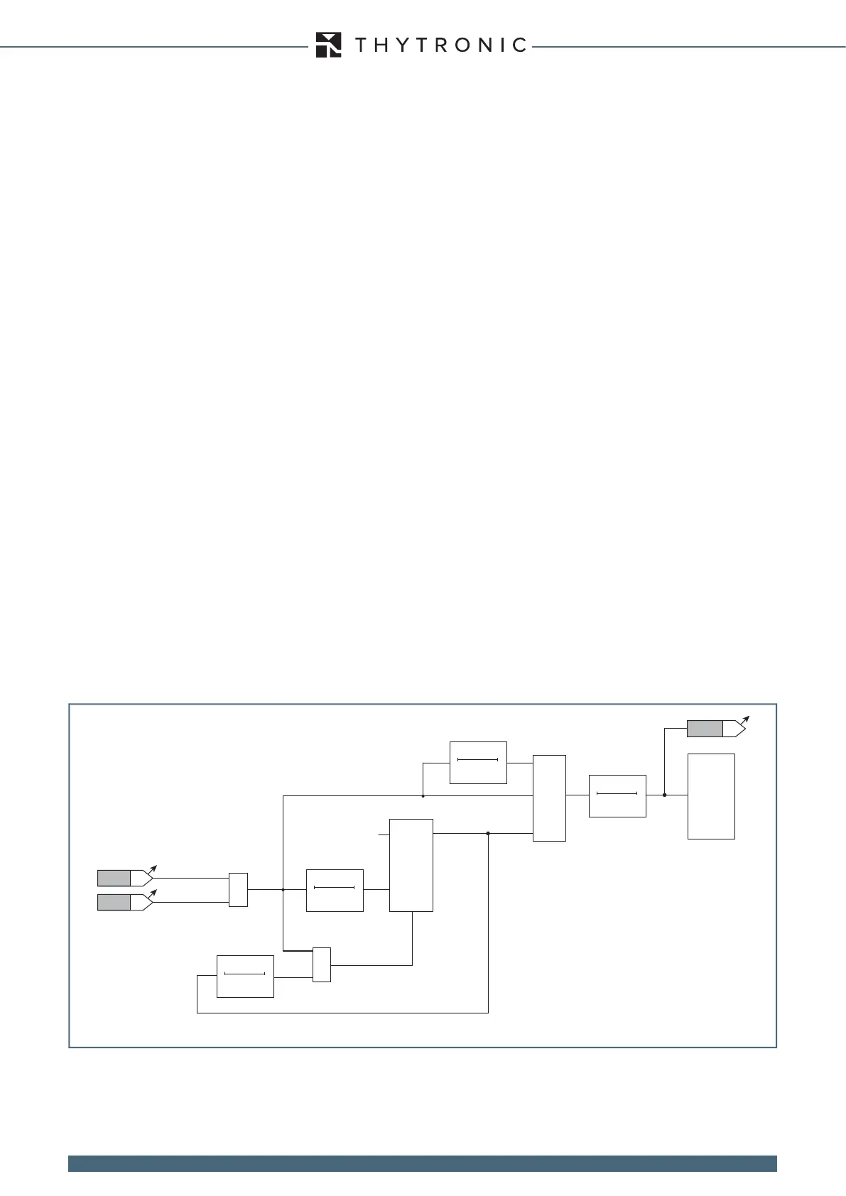
— Directional detection of intermittent ground arcs
The direction ground fault protection includes a function which detects intermittent arcing (67.S4)
using logical input signals 67N.S1 and 67N.S2, employing the logic indicated in the following gure,
in which:
• the two timers T1 and T2 output a high signal only if a high input signal persists for the indicated
time (T1= 100 ms, T2= 1500 ms),
• the timers T output the input signal and delay by the regulated time at drop-out (minimum 5 ms).
They have no specic function in the logic, other than to prevent possible incongruencies in chang-
es of state of the input signals to the OR logical port or the ip-op. This could result in pulse drop-
outs which prevent enabling delay timer T2 at the trip, or permanently enable resets of the ip-op,
thus making it impossible for port Q to transition to 1,
• The ip-op
- on the input (D) has a permanent high signal,
- on the input (R) has the reset signal which resets output signal Q
- on the output (Q) has:
- a null signal (=0) if there are no falling fronts on Ck (no single-phase ground fault or detection/
presence of a single-phase ground fault give a 0 signal on Ck)
- a high signal = 1 (equal to D permanently set to 1), when there is a falling front on Ck (the thresh-
olds IED> (67N.S1) and/or IED>> (67N.S2) drop out)
- a nul signal (=0) when the reset (R) is present
Functional diagram for the intermittent ground arcing detection function IED>>>> (67N.S4)
Ck
R
D Q
1
(drop-out delay)
(LED+RELAYS)
67.S4
≥
≥
≥
T 0
0.005 s
0 T
T1
T
(drop-out delay)
T
T2
0.1 s
0 T
1.5 s
T 0
0.005 s
IED>
IED>>
 Loading...