48
48
SME2-IS - Manual - 06 - 2021
FUNCTIONAL CHARACTERISTICS
— Synchrocheck - 25
Foreword
The synchrocheck function checks that the connection between two grids can be made without
risking the stability of the power system.
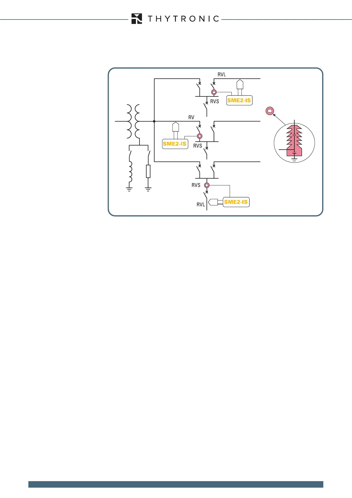
The reference voltage is measured upline of the breaker using a capacitive input.
Measurement inputs
The grid voltages measured at the inputs are used:
• V
1
reference voltage, measured by sensors, set to U
L1
, U
L2
or U
L3
in the menu Set \ Base
• V
2
phase voltage measured by the capacitive voltage divider.
Output relays
The synchrocheck function can activate one or more output relays according to the usual assign-
ment criterion.
Symbols
• t
STAB
minimum stabilisation time,
• t
CB-CLOSE
breaker closing time,
• timeout-
SYNC
synchronisation attempt timeout,
• t
SYNC
synchrocheck issue delay,
• V
max-SYNC
upper voltage threshold,
• V
min-SYNC
lower voltage threshold,
• f
RANGE
maximum frequency range relative to nominal frequency,
• Rof>
SYNC
maximum frequency difference between frequency measurements
(stability),
• df
-GRID
maximum frequency difference threshold to determine whether the grids are
synchronous,
• df12
-SYNC
maximum frequency difference threshold for frequency V1 > frequency V2,
• df21
-SYNC
maximum frequency difference threshold for frequency V2 > frequency V1,
• dV12
-SYNC
maximum voltage difference threshold for voltage V1 > voltage V2,
• dV21
-SYNC
maximum voltage difference threshold for voltage V2 > voltage V1,
• dp12
-SYNC
maximum phase shift threshold for V2 in advance of V1,
• dp21
-SYNC
maximum phase shift threshold for V1 in advance of V2,
• V1>
SYNC
voltage present threshold V1,
• tV1>
SYNC
tripping time V1>
SYNC
,
• V2>
SYNC
voltage present threshold V2,
• tV2>
SYNC
tripping time V2>
SYNC
,
• V1<
SYNC
voltage absent threshold V1,
• tV1<
SYNC
tripping time V1<
SYNC
,
• V2<
SYNC
voltage absent threshold V2,
• tV2<
SYNC
tripping time V2<
SYNC
,
Operation
The synchrocheck is run between two sections of the system, both of which are powered.
The devices uses the measured difference in frequency between the two grids to determine whether
the grids are synchronous or asynchronous.
Synchronous grids
For synchronous grids the nal relay is commanded (synchronisation ok) when the following con-
ditions obtain:
• The activation signal is active,
• the blocking input signal is inactive,
CAPACITIVE
VOLTAGE
DIVIDER
 Loading...