--INTRODUCTION HOW TO TROUBLESHOOT ECU CONTROLLED
SYSTEMS
IN --17
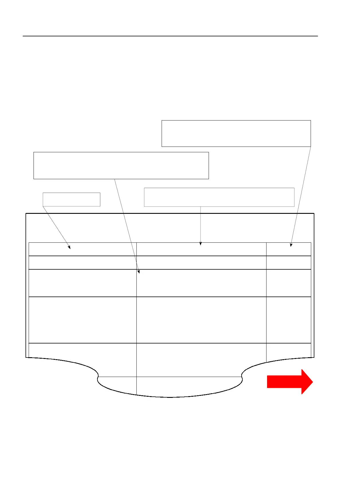
5. PROBLEM SYMPTOMS TABLE
The suspect circuits or parts for each problem symptom are shown in the table below. Use this table to trou-
bleshoot the problem when a ”Normal” code is displayed in the diagnostic trouble code check but the prob-
lem is still occurring. Numbers in the table indicate the inspection order in which the circuits or parts should
be checked.
HINT:
When the problem is not detected b y the diagnostic system even though the problem symptom is present,
it is considered that the problem is occurring outside the detection range of the diagnostic system, or that
the problem is occurring in a system other than the diagnostic system.
Symptom
Suspect Area
See page
Engine does not crank (Does not start)
No initial combustion (Does not start)
1.Starter
2. Starter relay
1. ECU power source circuit
2. Pre--heating system
3. Compression
4. Engine ECU
1. Pre--heating system
2. Starter signal circuit
3. Water temperature sensor
4. Injector
5. Fuel filter
6. Diesel throttle body
7. Engine ECU
ST--3
ST--14
DI--93
ST--1
EM--2
IN--20
PROBLEM SYMPTOMS TABLE
1. Starter signal circuit
2. Injector
3. Fuel filter
4. Diesel throttle body
5. Engine ECU
Cold engine (Difficult to start)
ST--1
DI--115
ED--10
FU--1
DI--26
IN--20
DI--115
D Problem Symptom
D Page
Indicates the page where the flow chart for each circuit
is located.
D Circuit Inspection, Inspection Order
Indicates the circuit which needs to be checked for each problem
symptom. Check in the order indicated by the numbers.
D Circuit or Part Name
Indicates the circuit or part which needs to be checked.
Hot engine
1. Fuel filter
2. Diesel throttle body
3 Engine ECU
CLICK HERE TO VIEW CHAPTER INDEX
Pages From Manual
TO MODEL INDEX
1KZ-TE
CONTINUED