EM0QP-- 02
A11050
Vacuum
Gauge
Actuator
VSV No.1
VSV No.2
A11051
Chamber A
Chamber B
Link
Fully Closed
Fully Open
EM--10
--ENGINE MECHANICAL INTAKE CONSTRICTOR CONTROL
INTAKE CONSTRICTOR CONTROL
INSPECTION
1. INITIAL CONDITIONS
(a) Engine at normal operating temperature
(b) Air cleaner installed
(c) All pipes and hoses of air induction system connected
(d) All accessories switched OFF
(e) All vacuum lines properly connected
(f) ECD system wiring connectors fully plugged
(g) Valve clearance set correctly
(h) Injection timing set correctly
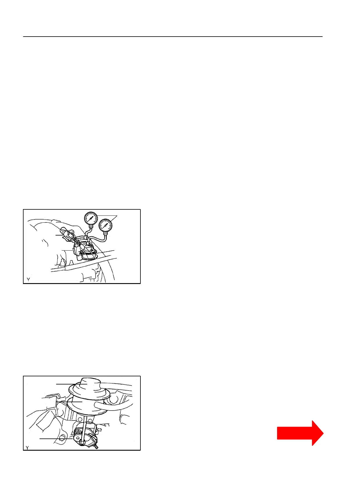
2 . CO NNE CT VACUUM G AUG E S
Using a 3-- way connector, connect a vacuum gauge to the hose
between the a ctuator and VSV.
NOTICE:
Always stop the engine when installing or removing the
vacuum gauge, or removing the vacuum hoses.
3. INSPECT COLD E NGINE CONDITION
(a) Start the engine.
(b) Check that the vacuum gauge in the chambers A and B
will not move.
HINT:
A no vacuum is loaded in the chamber, sub--throttle valve is fully
open.
(c) Check the lever link position of the illustration.
Standard:
Link is levered lowest position.
(Same position as that before staring)
CLICK HERE TO VIEW CHAPTER INDEX
Pages From Manual
TO MODEL INDEX
1KZ-TE
CONTINUED

 Loading...