B02134
WIRING DIAGRAM
D Wiring Diagram
DTC 12
CIRCUIT DESCRIPTION
The crankshaft positi on sensor in the Engine Control System contains signal plate and a pickup coil for TDC signal.
The TDC s ignal plate has 1 tooth on its outer circumference. The TDC signal sensor generates 1 signal for every engine
revolution. The engi ne ECU detects the top dead center by the TDC signals. The NE signal plate has 52 teeth and is
mounted in the supply pump. The NE signal sens or generates 52 signal s of engine 2 revolutions. The engine ECU detects
the engine speed and cam lift position of the s upply pump. The engine E CU uses TDC signal and NE signals for injection
control. And NE signal i s used for injecti on volume control, also.
DTC No. DTC Detecting Condition Trouble Area
12
No TDC signal to engine ECU at 500 rpm or more
D Open or short in crankshaft position sensor
circuit
D Crankshaft position sensor
D Engine ECU
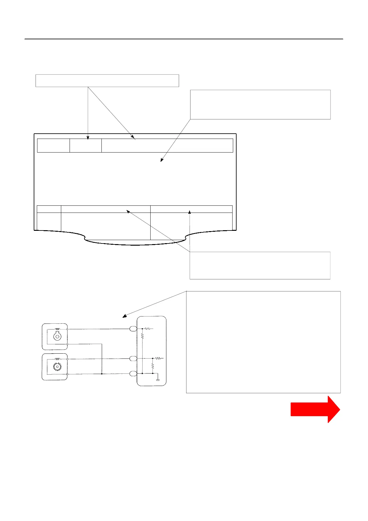
D Diagnostic Trouble Code No. and Detection Item
D Circuit Description
The major role and operation, etc. of the circuit
and its component parts are explained.
D Indicates the diagnostic trouble code, diagnostic
trouble code set parameter and suspect area of
the problem.
Crankshaft Position Sensor
1
2
1
2
Engine Speed Sensor
(inside the Suppy Pump)
B--W
L
B--R
B--R
BR L
E7
E7
E7
5
6
6
Engine ECU
G22+
NE+
NE--
E2
This shows a wiring diagram of the circuit.
Use this diagram t oget her wit h E LECT RI CA L
WIRING DIAGRAM to thoroughly understand the
circuit.
Wire colors are indicated by an alphabetical code.
B = Black, L = Blue, R = Red, BR = Brown,
LG = Light Green, V = Violet, G = Green,
O = Orange, W = White, GR = Gray, P = Pink,
Y = Yellow
The first letter indicates the basic wire color and the
second letter indicates the color of the stripe.
Crankshaft Position Sensor Circuit Malfunc-
tion
IN --18
--INTRODUCTION HOW TO TROUBLESHOOT ECU CONTROLLED
SYSTEMS
6 . CI RCUI T I NSPECTION
How to read and use each page is shown below.
CLICK HERE TO VIEW CHAPTER INDEX
Pages From Manual
CONTINUED
TO MODEL INDEX
1KZ-TE
 Loading...