 Loading...
Do you have a question about the Trane RTHC and is the answer not in the manual?
Explains the EPA mandated process of removing refrigerant from units.
Describes cleaning recovered refrigerant for reuse in customer equipment.
Details the purification and testing of refrigerant to ARI standards.
Details procedures for minimizing refrigerant emissions.
Provides essential safety warnings and cautions for servicing the RTHC unit.
Explains how to identify unit information using nameplates.
Details the process for inspecting the unit upon delivery.
Explains the RTHC chiller model number designation system.
Discusses factors for choosing the optimal installation location.
Specifies necessary space around the unit for service and operation.
Critical safety warning about using appropriate lifting equipment.
Details how to make water piping connections to the evaporator and condenser.
Warning about using untreated or improperly treated water, and potential damage.
Caution about the importance of installing pressure relief valves for shell safety.
Guidelines for proper electrical component operation and installation location.
Guidance on sizing and selecting power supply wiring according to NEC standards.
Emphasizes the importance of verifying correct compressor motor rotation before starting.
Explains the function and application of solid-state starters in RTHC chillers.
Critical safety warning about high voltage present at terminals even when off.
Explains how the chiller module controls the chilled water pump starter.
Describes the dry contact input for immediate chiller shutdown.
Explains how to adjust chilled water setpoint from a remote location using analog input.
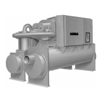
Provides an overview of the Series R chiller's basic components.
Describes the chiller's refrigeration cycle using a pressure-enthalpy diagram.
Describes the hermetic induction motor that drives the compressor rotors.
Explains how slide valve movement regulates compressor capacity.
Describes the function and operation of the oil separator.
Details how oil flow is protected and monitored within the system.
Introduces the UCP2 system for chiller control, protection, and optimization.
Details the CLD operator interface for displaying data and accessing controls.
Explains access to chiller information via Report Groups (Chiller, Refrigerant, Compressor).
Describes access to settings and commands through four major Settings Groups.
Accesses non-password protected service settings.
Manages the password protection for menu settings.
Enables locking the keypad and display for security.
Sets the design delta temperature based on initial selection and operating conditions.
Sets the timer to prevent excessive chiller cycling.
Sets the first current overload setting for motor protection.
Sets the timer for motor acceleration during startup.
Sets the high-pressure cutout limit for the system.
Provides access to tests and manual overrides for chiller subsystems.
Step-by-step procedure for daily unit start-up.
Details the procedure for daily unit shutdown.
Procedure for seasonal unit shutdown.
Describes preventive maintenance procedures and intervals for Series R units.
Procedures for weekly chiller checks and logging.
Procedures for monthly chiller checks and operating log review.
Annual maintenance tasks to ensure unit performance and efficiency.
Information related to the starter data for start-up.
Compressor data required for start-up.
Nameplate data including RLA, KW, Volts.
Design data including RLA, KW, Volts.
Lists design conditions for evaporator and condenser.
Checklist items for unit receiving.
Checklist items for unit location and mounting.
Checklist items for unit piping installation, including flushing precautions.
Checklist items for electrical wiring, including safety warnings.
Checklist items for pre-start check-out.
Procedures for cleaning the condenser.
Safety precautions and procedure for removing compressor oil.
Procedure to measure the oil level in the oil sump.
Procedure for removing compressor oil, with storage precautions.
Procedure for charging oil into the system, emphasizing filling oil lines.
Procedure for replacing the main oil filter based on pressure drop.
Procedure for addressing suspected low refrigerant charge.
Steps for evacuating and dehydrating the system.
Procedure for adding refrigerant charge to the system.
Measures for protecting the unit against freezing in low-temperature environments.
Information on viewing active and historic diagnostics.
Notifies the operator of new diagnostics detected by the system.
Details active diagnostics, including their causes and help messages.
Provides screens to clear and reset diagnostic groups.
Introduces typical field connection and electrical schematic diagrams.
Explains how to find specific electrical characteristics from unit nameplates.