2 - 26 RTHC-IOM-1C
NOTE: The UCP2 provides a 6-second time delay on
the flow switch input before shutting down the unit on
a loss-of-flow diagnostic. Contact a qualified service
organization if nuisance machine shutdowns persist.
q Adjust the switch to open when water flow falls
below nominal. Refer to the General Data table in
Section 1 for minimum flow recommendations for
specific water pass arrangements. Flow switch
contacts are closed on proof of water flow.
Refrigerant Pressure Relief Valve Venting
To prevent injury due to inhalation
of HFC-134 gas, do not discharge
refrigerant anywhere. If multiple
chillers are installed, each unit
must have separate venting for its
relief valves. Consult local regula-
tions for any special relief line
requirements.
NOTE: Vent pipe size must conform to the ANSI/
ASHRAE Standard 15 for vent pipe sizing. All
federal, state, and local codes take precedence over
any suggestions stated in this manual.
All relief valve venting is the responsibility of the
installing contractor.
All RTHC units use evaporator, compressor, and
condenser pressure relief valves (
Figure 17
) that
must be vented to the outside of the building.
Relief valve connection sizes and locations are
shown in the unit submittals. Refer to local codes for
relief valve vent line sizing information.
CAUTION: Do not exceed vent piping
code specifications. Failure to heed
specifications could result in capacity
reduction, unit damage and/or relief
valve damage.
Relief valve discharge setpoints and relief rates are
given in
Table 12
. Once the relief valve has opened,
it will reclose when pressure is reduced to a safe
level.
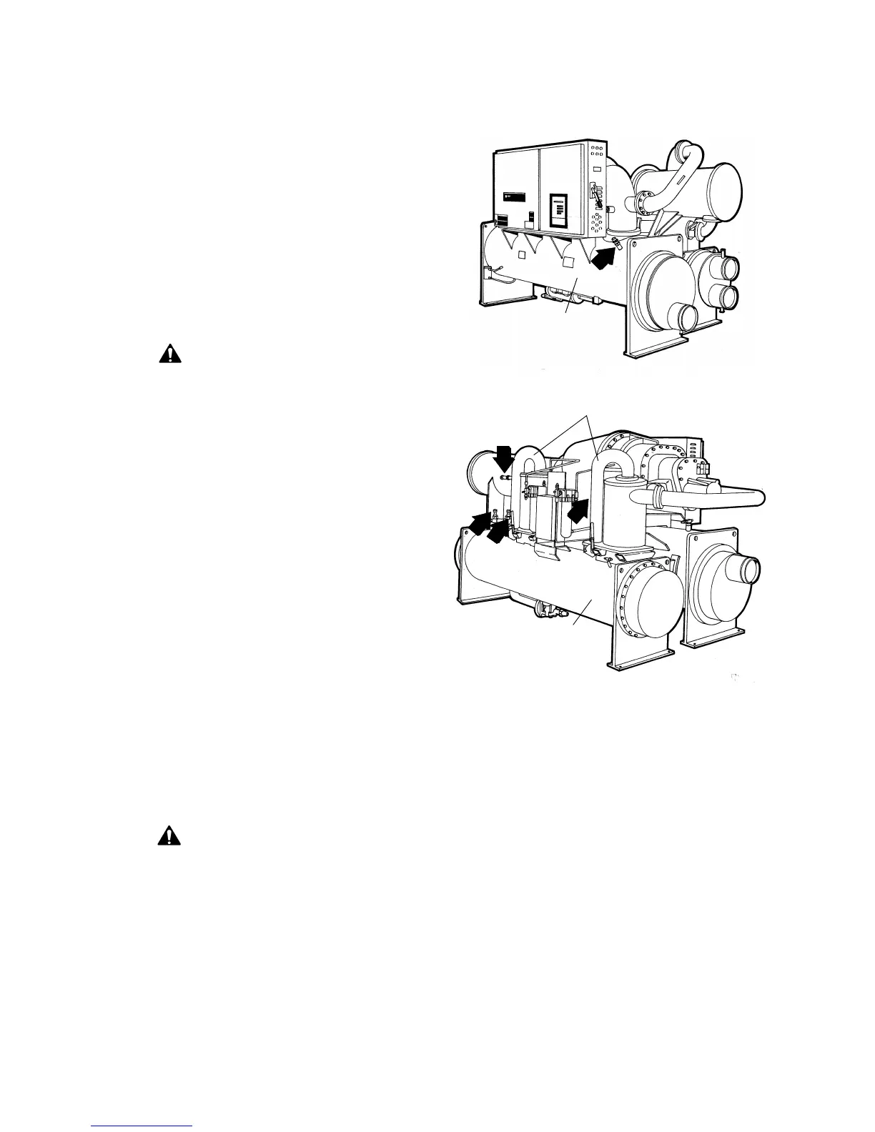
Figure 17
Relief Valve Locations
NOTE: Once opened, relief valves tend to leak and
must be replaced.
Pressure relief valve discharge setpoints and relief
rates will vary with shell diameter and length and also
compressor displacement. Relief rates should be
calculated as required by ASHRAE Standard 15-94
Evaporator Shell
Condenser Shell
Discharge Pipes
*
* Valve is hidden by pipe
 Loading...


