3 - 10 RTHC-IOM-1C
external auto stop input is closed and opens when
the timeout period, specified in the Service Settings
group, expires after the external auto stop input
opens.
Chilled Water Flow Interlock
The chiller module (1U1) requires a control voltage
contact input (1TB3-14, J26-1) through a flow proving
switch (5S1) and an auxiliary contact (5K1 AUX) from
the chilled water pump starter that provides proof of
flow.
IMPORTANT! DO NOT cycle the chiller through
starting and stopping the chilled water pump. This
will cause the compressor to shut down fully loaded.
Use the externalstop/start input to cycle the chiller.
Condenser Water Pump Control*
The chiller module (1U1) provides a contact closure
output (J14-1, J14-2) to control the condenser water
pump starter. This contact closure pulls in anytime
the UCP2 generates a need for cooling based on the
leaving chilled water temperature versus setpoint
and opens when the compressor is stopped.
Condenser Water Flow Interlock
The chiller module (1U2) requires a control voltage
contact input (1TB3-15, J28-2) through a flow proving
switch (5S2) and an auxiliary contact (5K2 AUX) from
the condenser water pump starter that provides proof
of flow.
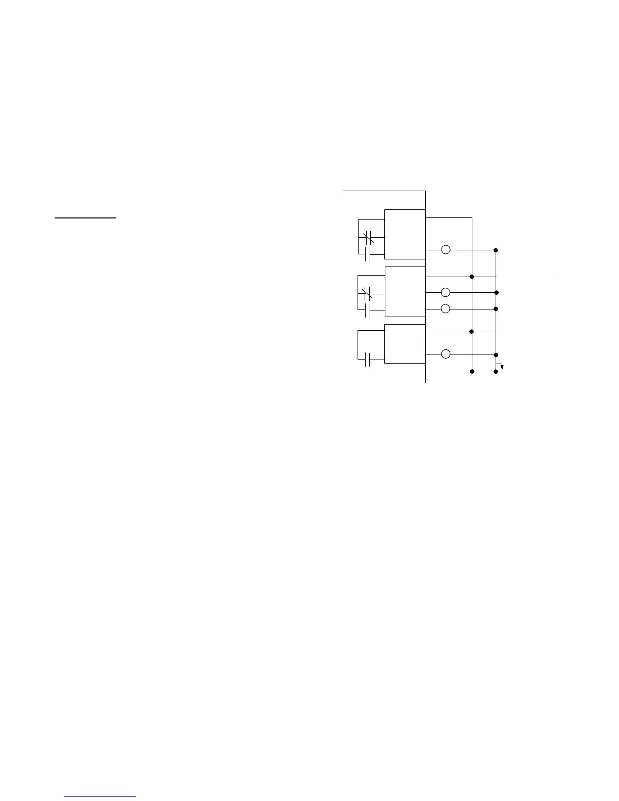
NOTE: The following three connections have
programmable functions. Each relay can be
configured individually as an alarm contact,
compressor contact, or a limit warning contact.
Their default functions are described as follows.
See Section 5, Service Settings for details on
other functions that can be assigned to these
contacts.
Relay 1 - Programmable*
The chiller module (1U1) provides a normally open
(J16-3, J16-1) and a normally closed (J16-3, J16-2)
contact closure output that may be used to remotely
indicate the compressor is running in any mode
except Run Unload.
Relay 2 - Programmable*
The chiller module (1U1) provides a normally open
(J18-3, J18-1) and a normally closed (J18-3, J18-2)
contact closure output that may be used to remotely
indicate a latching diagnostic exists.
Relay 3 - Programmable*
The chiller module (1U1) provides a normally open
(J20-2, J20-1) contact closure output that may be
used to remotely indicate a load limit condition
(condenser, evaporator or current) existed for more
than 20 minutes.
Figure 23
RTHC Electrical Installation Programmable Relays
Outdoor Air Temperature Sensor
The chiller module (1U1) provides for connection (J5-
5, J5-6) of an outdoor air temperature sensor (5RT1)
that may be used for outdoor air chilled water reset.
The UCP2 contains the logic required, based on
menu items selected, to perform these functions.
External Auto Stop
The chiller module (1U1) provides a dry contact input
(J5-1, J5-2) that must be used to enable or disable
the chiller from a remote location, unless a Tracer is
performing this function. If this feature is not used, a
jumper must be placed across this input. If the chilled
water pump is controlled by the UCP2 (chiller module
J12-2, J12-1), the external auto stop will start and
stop the pump as described above.
Emergency Stop
The chiller module (1U1) provides a dry contact input
(J5-3, J5-4) that may be used to immediately shut the
chiller down. If this feature is not used, a jumper must
be placed across this input.
This method of
stopping the chiller should only be used for
emergency shutdowns
, because the slide valve will
Relay 1
Relay 2
Relay 3
J16-3
J16-2
J16-1
J18-3
J18-2
J18-1
J20-2
J20-1
1U1
H
N
Customer-provided 115VAC
Power; Max fuse Size: 15 amp
 Loading...


