5 - 26 RTHC-IOM-1C
the other must be changed also and the sum of the
two must always be 255.
Current Overload Setting #2
The range of values is decimal 224 through 255. The
ROM default is 255. For security purposes the
second setting is the 8-bit one’s complement of the
first setting above. Both the maximum acceleration
timers and the overload settings are not adjustable
from either the remote CLD or Tracer or any other
remote/external device.
Maximum Acceleration Timer #1
This value indicates the time at which the UCP2
expects full acceleration of the motor to occur either
under part-winding phase of the Y-Delta start
sequence or under current limit control of the solid
state starter.
The range of values is 2 to 64 Sec. The ROM default
is 6 seconds. Refer to the table following for proper
settings based on compressor size. Both the
maximum acceleration timers and the overload
settings are not adjustable from either the remote
CLD or Tracer or any other remote/external device.
Adjusting this value to a longer time than suggested
for a particular compressor, is not recommended as it
can compromise the motor protection. Failure of the
motor to fully accelerate within this time will cause
either an aborted start, or an immediate starter
transition or bypass depending on the setting of the
Acceleration Time Out Action (entry below). In either
case, an appropriate diagnostic is generated.
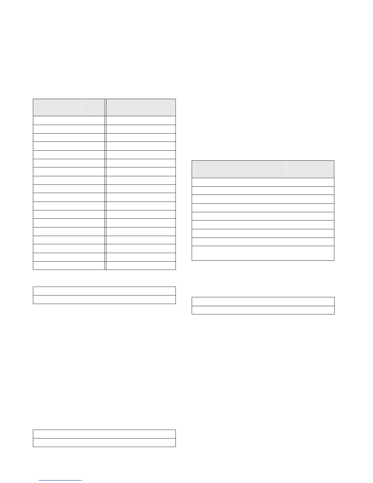
Table 19
Recommended Max. Acceleration Timer Settings
Maximum Acceleration Timer #2
The range of values is 191 to 253 sec. The ROM
default is 249. Timer #1 and Timer #2 settings must
equal 255. Both the maximum acceleration timers
and the overload settings are not adjustable from
either the remote CLD or Tracer or any other remote/
external device.
Table 18
Current Overload Settings #1 and #2 as a Function of CT
Factor
CT
Factor
Setting
#1
Setting
#2
CT
Factor
Setting
#1
Setting
#2
66 00 255 84 19 236
67 01 254 85 20 235
68 02 253 86 21 234
69 03 252 87 22 233
70 04 251 88 22 233
71 06 249 89 23 232
72 07 248 90 24 231
73 08 247 91 25 230
74 09 246 92 25 230
75 10 245 93 26 229
76 11 244 94 27 228
77 12 243 95 28 227
78 13 242 96 28 227
79 15 240 97 29 226
80 15 240 98 30 225
81 16 239 99 30 225
82 17 238 100 31 224
83 18 237
Current Overload Setting #2: xx
Press (+)(-) to Change Setting
Maximum Acceleration Timer #1: xx sec
Press (+)(-) to Change Setting
Compressor
Max Accel Timer
#1
Max Accel Timer
#2
B1 3 252
B2 3 252
C1 5 250
C2 5 250
D1 6 249
D2 6 249
D3 6 249
E3 6 249
ALL Sizes with
Solid State Starter
6 249
Maximum Acceleration Timer #2: xxx sec
Press (+)(-) to Change Setting
 Loading...


