4 - 6 RTHC-IOM-1C
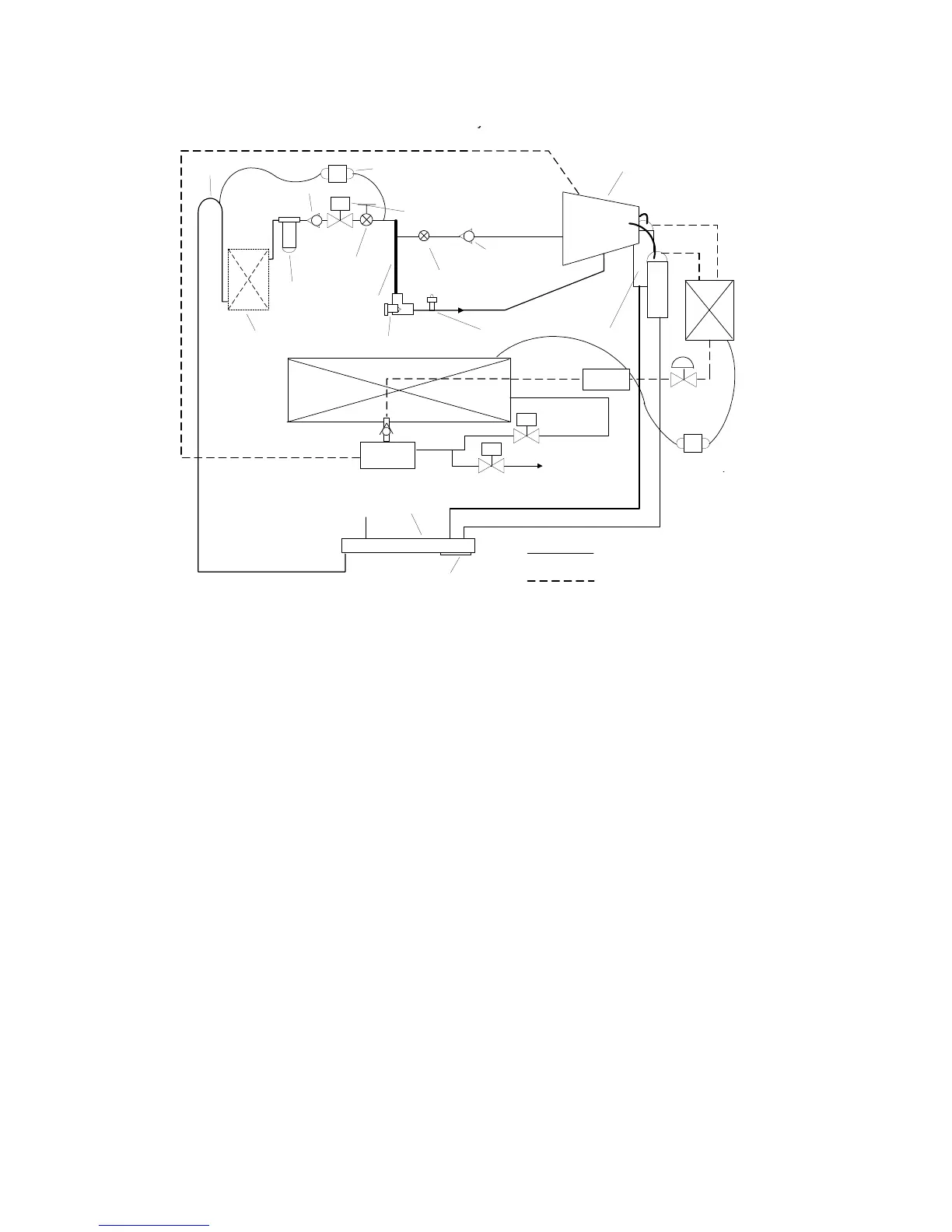
Figure 28
Oil Flow Diagram
Oil that collects in the oil tank sump is at condensing
pressure during compressor operation; therefore, oil
is constantly moving to lower pressure areas.
Oil Flow Protection
Oil flowing through the lubrication circuit flows from
the oil sump to the compressor (see
Figure 28
). As
the oil leaves the oil sump, it passes through two
service valves, an oil cooler (if used), oil filter, and
master solenoid valve. Oil flow then splits into two
distinct paths, each performing a separate function:
(1) bearing lubrication and cooling, and (2)
compressor oil injection.
Oil flow and quality is proven through a combination
of a number of sensors, most notably two differential
pressure switches and the optical oil level sensor.
If for any reason oil flow is obstructed because of a
plugged oil filter, closed service valve, faulty master
solenoid, or other source, a differential pressure (DP)
switch will give a “high” reading (as factory-
calibrated) and shut down the chiller. The differential
pressure switch is factory set to open and trip on a
pressure rise above 20 psid for systems without an
oil cooler and 35 psid for systems with an oil cooler.
Likewise, the optical oil level sensor can detect the
lack of oil in the primary oil system (which could
result from improper oil charging after servicing, or oil
logging in other parts of the system). The sensor can
prevent the compressor from starting or running
unless an adequate volume of oil is present. The
combination of these two devices, as well as
diagnostics associated with extended low system
differential pressure and low superheat conditions,
can protect the compressor from damage due to
severe conditions, component failures, or improper
operation.
If the compressor stops for any reason, the master
solenoid valve closes; this isolates the oil charge in
the sump during “off” periods. The check valves in
the primary oil system prevent reverse flow that the
solenoid valve may be unable to contain or “injector-
to-bearing” oil flow immediately following compressor
shutdown. Such flows would otherwise clear out oil
from the lines and the oil sump, which is an
undesirable effect.
To ensure the required system differential pressure is
adequate to move oil to the compressor, the UCP2
monitors both the 7.7 psid differential switch mounted
between the evaporator and the condenser and the
temperature sensors mounted in both the evaporator
Evaporator
Compressor
Restrictor
Orifice
Oil Sump
Oil Filter
Optional Oil
Cooler
Oil Heater
Trap
Master Oil Line
Solenoid
Oil Separators
Optical Oil
Detector
Vent
Oil Charging
Service Port
To Bearings
Injection to
Rotors
Check Valve
Oil Return
Gas Pump
Vent Line
To Condenser
Pressure
Oil/Refrigerant Mixture
Oil Recovery
Fill Solenoid
Valve
Drain Solenoid
Valve
Oil/Refrigerant
Mixture
Condenser
EXV
Primary Oil System
Refrigerant & Oil Mixture-
Oil Recovery System
Oil Flow
Loss DP
Switch
Check Valve
Manual
Service
Valve
Large
capacity
vertical line
Low Diff
Rfgt Pres
Switch
LVS
 Loading...


