5 - 2 RTHC-IOM-1C
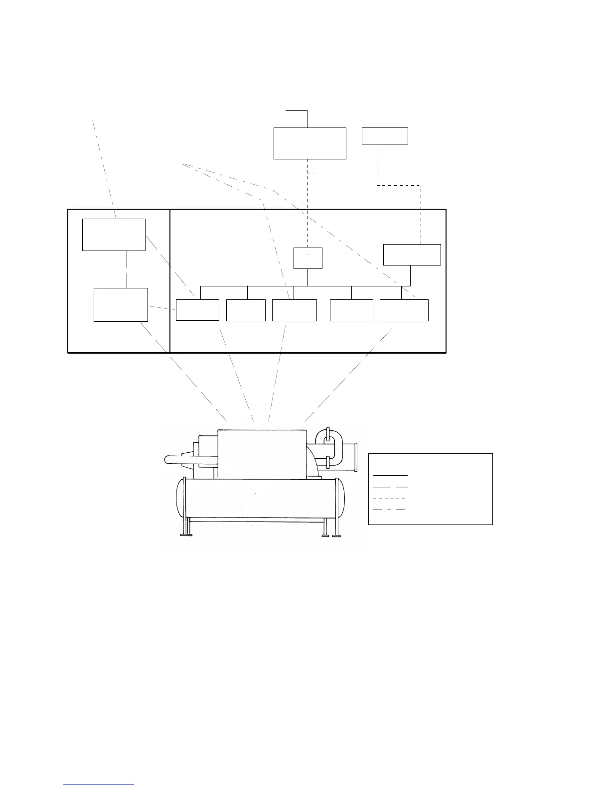
Figure 29
Control System Block Diagram.
Chiller Module - 1U1
The chiller module is the central processing unit of
the chiller communicating commands to other
modules and collecting data/status/diagnostic
information from other modules over the IPC (inter
processor communications) link. The chiller module
performs the leaving chilled water temperature and
limit control algorithms, setting capacity against any
operating limit constraining the chiller.
The chiller module contains non-volatile memory,
checking for valid set points and retaining them on
any power loss.
Inputs and outputs include chilled water system level
input/output (I/O) such as evaporator and condenser
Clear
Language
Display
Stepper Mod.
EXV
IPC
Options Mod.
(Opt.)
Tracer(Comm 3)
or Summit (Comm 4)
(Optional)
TCI IV
(Opt.)
Comm 3 or
Comm 4
To Other UCMs
ICS Proprietory
Unit Proprietary
Industry Std Interface
To Other Tracer
or Other BAS
Printer
RS232
Printer Interface
Mod. (Opt.)
Control Section
Starter/Control Panel
Hard Wired
Customer
Interfaces
Line Power
Hard Wired Factory
Connections
KEY
Factory Wired Serial Comm
Customer Wired Serial Comm
Factory Hard Wired
Customer Hard Wired
Y-D or Solid
State Starter
Starter Section
Starter Mod.
Circuit Breaker/
Disconnect/
Fuse / Terminal
Block Options
Chiller Mod
1U8 Buffer
1U6
1U7
1U2 1U1 1U3 1U5
1U4
 Loading...


