SECTION 4. METERS AND SWITCHES
1.METERS
1.1 Removal
a. Disconnect the cable from the negative post.
b. Remove the philips screw which hold the
meter panel and lift up the panel assembly a
little
Fig.10-3 Meter panel
The generated pulses are converted into voltage
output through a converter. Then the voltage is
divided into three different phase coils through a
IC circuit. The tachometer pointer is swung by
the compound magnetic field generated by the
three point.
b. Inspection
-Tachometer
The allowable error of a tachometer reading is
specified as shown on the table below.If the
reading deviates from the specified value.replace
the meter assembly.
Engine speed(rpm) 1000 2500
Allowable error(rpm)
±150 ±150
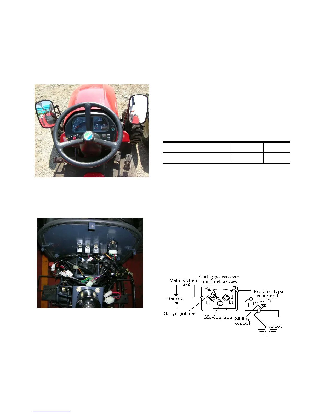
1.3 Fuel gauge and Fuel gauge sensor
a.Construction
10-5
removing the wire harness couplings.
Fig.10-4 Wire harness
1.2 Tacho/hour meter and sensor
a.Construction
An electric tachometer is employed along with a
Tachosensor. The tach/hour meter converts
engine revolutions to electric signals,which is
sent to the tachometer. The tachometer displays
the engine revolutions visually.The tachosensor
generates
14 pulses per one engine revolution.
When the fuel tank is full,the float is at the top
and has moved the variable resister to a position
of least resistance. This feeds maximum current
into the meter circuit and the pointer swings
fully to the F position. Consequently when the
fuel level in the tank is low, everything acts in
reverse.
Fig.10-5 Fuel gauge sensor
 Loading...