EasyManua.ls Logo

Universal Robots UR16e User Manual

Universal Robots UR16e
373 pages
To Next Page IconTo Next Page
To Previous Page IconTo Previous Page
Page #245 background imageLoading...
Page #245 background image
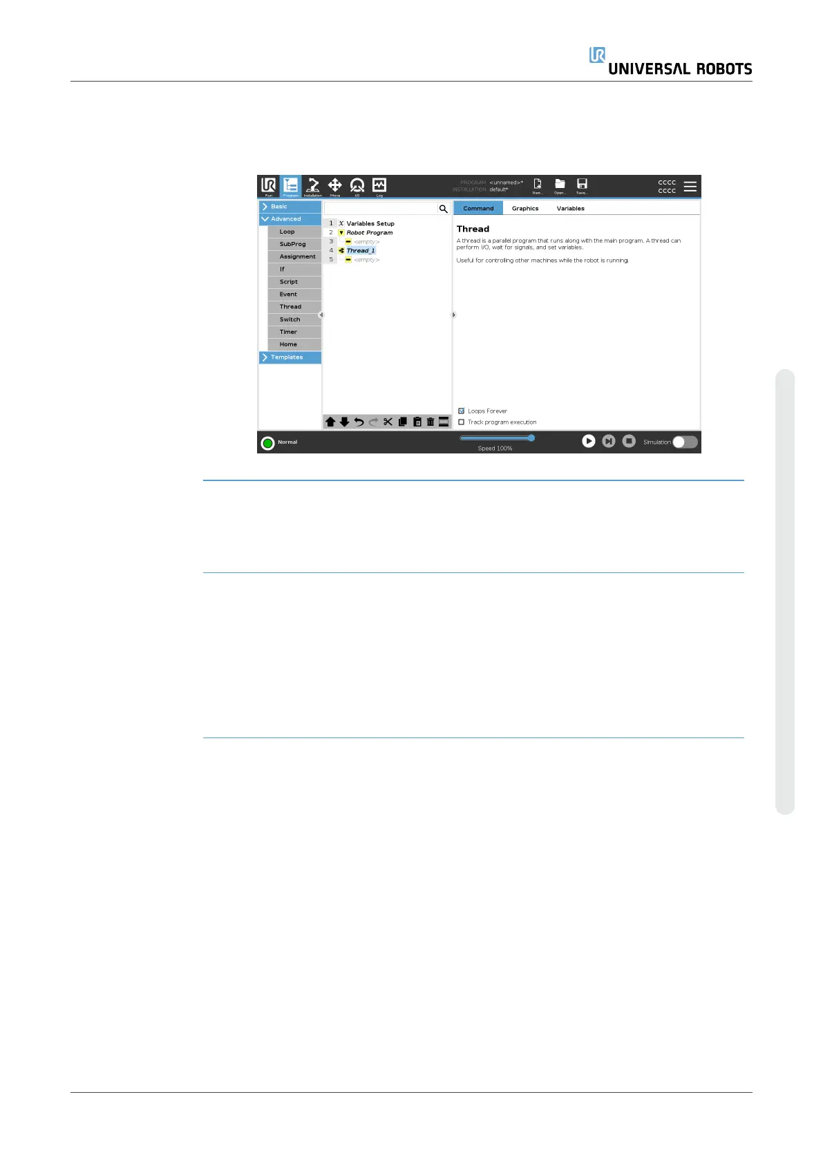
Description A thread is a parallel process to the robot program. A thread can be used to
control an external machine independently of the robot arm. A thread can
communicate with the robot program with variables and output signals.
7.8.8. Switch
Description A Switch Case construction can make the robot change behavior based on
sensor inputs or variable values.
Use the Expression Editor to describe the base condition and define the
cases under which the robot should proceed to the sub-commands of this
Switch.
If the condition is evaluated to match one of the cases, the lines inside the
Case are executed. If a Default Case has been specified, then the lines
will be executed only if no other matching cases were found.
User Manual 245 UR16e
Copyright © 2009–2024 by UniversalRobotsA/S. All rights reserved.

Table of Contents

Other manuals for Universal Robots UR16e

Questions and Answers:

Universal Robots UR16e Specifications

General IconGeneral
BrandUniversal Robots
ModelUR16e
CategoryRobotics
LanguageEnglish

Summary

1. Preface

Important Safety Notice

Highlights that the robot is partly completed machinery requiring a risk assessment for safe installation.

Part I Hardware Installation Manual

2. Safety

2.3. Safety Message Types

Explains the meaning of various safety warning symbols (Warning, Caution, Notice, etc.).

2.4. General Warnings and Cautions

Lists essential safety practices for robot operation, installation, and personnel protection.

2.5. Intended Use

Specifies the robot's intended industrial applications and limitations for safe operation.

2.6. Risk Assessment

Outlines the legal requirement and process for conducting risk assessments for robot applications.

2.7. Pre-Use Assessment

Details mandatory tests to verify safety functions before robot operation or after modifications.

2.8. Emergency Stop

Explains the function and operation of the emergency stop button on the Teach Pendant.

2.10. Safety-related Functions and Interfaces

Covers built-in safety functions, I/O, and control signals for connecting safety devices.

2.10.1. Stop Categories

Defines the three types of stop categories (0, 1, 2) initiated by the robot according to IEC 60204-1.

2.10.2. Configurable Safety Functions

Lists and describes robot safety functions like Joint Position Limit, Speed Limit, and Force Limit.

2.10.3. Safety Functions

Explains how the safety system reacts to limit violations and safety stop triggers.

2.10.4. Safety Parameter Set

Details the configurable safety parameters for Normal and Reduced modes.

3. Mechanical Interface

3.2. Mounting Description

Provides details on mounting the robot arm, tool flange, control box, and teach pendant.

3.3. Securing the Robot Arm

Details the dimensions and hole pattern for securely mounting the robot arm base.

3.6. Maximum Payload

Defines the robot's rated payload capacity and factors affecting acceleration capability.

4. Electrical Interface

4.1. Electrical Warnings and Cautions

Provides critical safety warnings related to electrical interfaces and PLC connections.

4.2. Controller I/O

Illustrates the layout of electrical interface groups inside the control box.

4.3. Safety I/O

Describes dedicated safety inputs and configurable I/O when used for safety functions.

4.4. Three Position Enabling Device

Explains the configurations for the three-position enabling device and operational mode switch.

6. Maintenance and Repair

6.2. Inspection

Outlines recommended regular inspections for the robot arm and control box.

9. Stopping Time and Stopping Distance

9.1. Robot Scenario 1: 10 kg.

Presents stopping distance and time data for the robot with a 10 kg payload at different extensions.

9.2. Robot Scenario 2: 12.5 kg.

Provides stopping distance and time data for the robot with a 12.5 kg payload at different extensions.

13. Applied Standards

IEC 60204-1

Standard for electrical equipment of machines, including emergency stop functions.

14. Technical Specifications

15. Safety Functions Table 1

SF1 Emergency Stop (according to ISO 13850)

Details the Emergency Stop function, its reaction, tolerance, and affects.

SF2 Safeguard Stop 4 (Robot Stop according to ISO 10218-1)

Describes the Safeguard Stop function initiated by external protective devices.

SF3 Joint Position Limit (soft axis limiting)

Sets upper and lower limits for allowed joint positions to prevent exceeding limits.

SF4 Joint Speed Limit

Sets an upper limit for joint speed, influencing energy transfer upon contact.

SF5 Called various names: Pose Limit, Tool Limit, Orientation Limit, Safety Planes, Safety Boundaries

Monitors TCP Pose and prevents exceeding safety planes or TCP Pose limits.

SF6 Speed Limit TCP & Elbow

Monitors TCP and elbow speed to prevent exceeding speed limits.

SF7 Force Limit (TCP)

Limits the force exerted by the robot at the TCP and elbow.

SF8 Momentum Limit

Limits transient impacts by controlling the robot's momentum.

SF9 Power Limit

Monitors mechanical work performed by the robot, dynamically limiting current/torque.

SF10 UR Robot Estop Output

Describes the dual output signal for robot emergency stop status.

SF11 UR Robot Moving: Digital Output

Details the dual digital output signal indicating robot movement status.

SF12 UR Robot Not stopping: Digital Output

Explains the dual digital output signal for robot stopping status.

SF13 UR Robot Reduced Mode: Digital Output

Describes the dual digital output signal for the robot's reduced mode status.

SF14 UR Robot Not Reduced Mode: Digital Output

Details the dual digital output signal for the robot's non-reduced mode status.

SF15 Stopping Time Limit

Monitors and limits the time required for the robot to stop.

SF16 Stopping Distance Limit

Monitors and limits the distance the robot travels during stopping.

SF17 Safe Home Position "monitored position"

Ensures output activation only when robot is in the configured safe home position.

15.1. Table 1a

3-Position Enabling Device INPUT

Describes the use of a 3-position enabling device for manual mode operation.

15.2. Table 2

Part II PolyScope Manual

16. Introduction

16.2. Robot Arm Installation

Provides step-by-step instructions for installing the robot arm, control box, and teach pendant.

16.6. Quick System Start-up

Provides a quick guide for starting up the robot and accessing the Initialize screen.

16.8. Robot Cyber Security

Covers principles and guidelines for implementing and hardening robot cyber security.

17. Software Safety Configuration

17.1. Setting a Software Safety Password

Details the process of setting a password to unlock and configure safety settings.

17.2. Changing the Software Safety Configuration

Outlines the recommended procedure for changing safety configuration settings.

17.3. Applying a New Software Safety Configuration

Explains how changes take effect after applying and restarting the robot.

17.5. Software Safety Modes

Describes the safety modes: Normal, Reduced, and Recovery, and their associated limits.

17.6. Software Safety Limits

Specifies how to define and configure safety system limits for robot operation.

17.6.1. Robot Limits

Details how to restrict general robot movements using Factory Presets or Custom options.

17.6.2. Joint Limits

Explains how to restrict individual robot joint movements in position and speed.

17.7. Safety I/O

Covers safety functions that can be used with input signals like Emergency Stop and Reduced Mode.

17.8. Software Safety Restrictions

Explains how to define safety planes to restrict robot workspace and tool movement.

17.8.1. Tool Direction Restriction

Details how to restrict the angle of the tool's pointing direction using a cone limit.

17.8.2. Tool Position Restriction

Explains how to restrict tools and accessories on the robot arm's end using controlled restrictions.

18. Run Tab

19. Program Tab

19.1. Robot Program Configuration

Covers configuration for the entire robot program, including startup instructions and loops.

19.7.1. Move

Details the Move command for controlling robot movement between points (waypoints).

19.7.2. Waypoints

Explains how waypoints define the robot's path and how to configure them.

19.7.10. Set Payload

Allows configuration of payload, CoG, and inertia for optimal robot performance.

19.9.2. Force

Enables applications requiring precise force control along a predefined axis.

20. Installation Tab

20.1. TCP Configuration

Defines a Tool Center Point (TCP) with translation and rotation relative to the tool flange.

20.1.1. Teaching TCP Position

Calculates TCP position coordinates by teaching points in the robot's workspace.

20.2. Payload

Sets Payload, Center of Gravity (CoG), and inertia for optimal robot performance.

Payload Estimation

Utilizes a wizard to help set correct Payload and Center of Gravity (CoG) values.

20.3. Mounting

Specifies the robot arm's mounting orientation to ensure correct screen appearance and gravity direction.

20.12. Safety

Refers to Chapter 17 for detailed information on Software Safety Configuration.

20.14.4. PROFIsafe

Covers the PROFIsafe network protocol for robot communication with a safety PLC.

21. Move Tab

Active TCP

Displays the name of the current active Tool Center Point (TCP) for robot movement.

Freedrive

Allows the robot arm to be pulled into desired positions/poses using the on-screen button.

21.1. Pose Editor Screen

Enables precise configuration of target joint positions or TCP poses (position and orientation).

22. I/O Tab

23. Log Tab

24. Program and Installation Manager

25. Hamburger menu

25.2.2. Password

Details password management for unlocking safety settings and administrator access.

25.2.4. Security

Manages security settings, including admin password, magic files, and network access.

26. Glossary

Risk assessment

The process of identifying and reducing all risks to an appropriate level.

Safety configuration

Parameters defining safety-related functions and interfaces, configured via the software interface.

Related product manuals