20.1.1. Teaching TCP Position
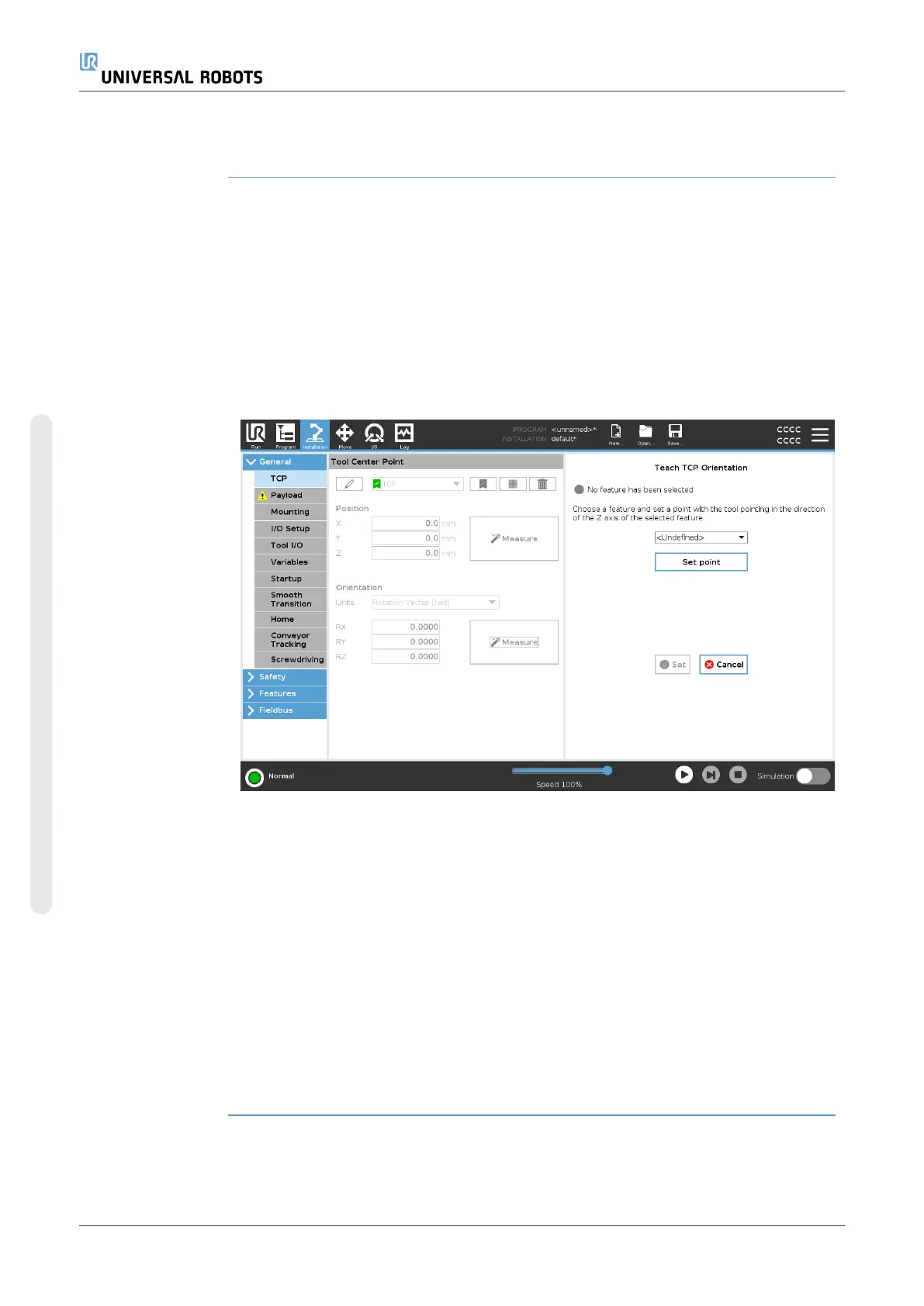
Teaching TCP
orientation
TCP position coordinates can be calculated automatically as follows:
1. Tap Measure.
2. Choose a fixed point in the workspace of the robot.
3. Use the position arrows on the right side of the screen to move the TCP from at
least three different angles and to save the corresponding positions of the tool
output flange.
4. Use the Set button to apply the verified coordinates to the appropriate TCP. The
positions must be sufficiently diverse for the calculation to work correctly. If they
are not sufficiently diverse, the status LED above the buttons turns red.
Though three positions are sufficient to determine the TCP, a fourth position can be
used to further verify the calculation is correct. The quality of each saved point, with
respect to the calculated TCP, is indicated using a green, yellow, or red LED on the
corresponding button.
1. Tap Measure.
2. Select a feature from the drop-down list. (See20.13 Featureson page299) for
additional information on defining new features
3. Tap Set point and use Move tool arrows to a position where the tool’s
orientation and the corresponding TCP coincide with the selected features’s
coordinate system.
4. Verify the calculated TCP orientation and apply it to the selected TCP by tapping
Set.
UR10e 280 User Manual
Copyright © 2009–2024 by UniversalRobotsA/S. All rights reserved.
 Loading...


