4.15. Tool Digital Outputs
Description Digital Outputs support three different modes:
Mode Active Inactive
Sinking (NPN) Low Open
Sourcing (PNP) High Open
Push / Pull High Low
Access Tool I/O in the Installation Tab (see partPart II PolyScope Manual) to configure
the output mode of each pin. The electrical specifications are shown below:
Parameter Min Typ Max Unit
Voltage when open -0.5 - 26 V
Voltage when sinking 1A - 0.08 0.09 V
Current when sourcing/sinking 0 600 1000 mA
Current through GND 0 1000 3000* mA
NOTICE
Once the robot makes an Emergency Stop, the Digital Outputs (DO0
and DO1) are deactivated (High Z).
CAUTION
The Digital Outputs in the tool are not current-limited. Overriding the
specified data can cause permanent damage.
Using Tool Digital
Outputs
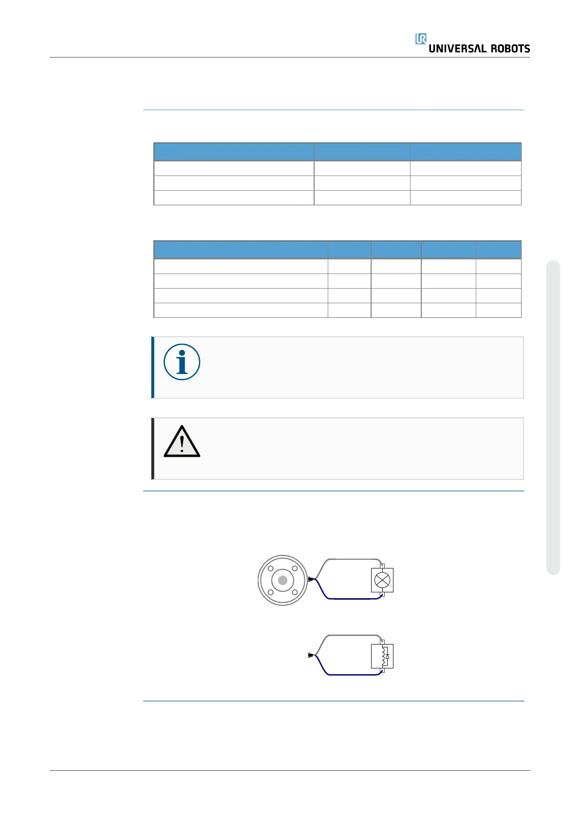
This example illustrates turning on a load using the internal 12V or 24V power supply.
The output voltage at the I/O tab must be define. There is voltage between the POWER
connection and the shield/ground, even when the load is turned off.
It is recommended to use a protective diode for inductive loads, as shown below.
User Manual 67 UR10e
4. Electrical Interface
Copyright © 2009–2024 by UniversalRobotsA/S. All rights reserved.
 Loading...


