4.6. General Purpose Analog I/O
Description The analog I/O interface is the green terminal. It is used to set or measure voltage (0-
10V) or current (4-20mA) to and from other equipment.
The following directions is recommended to achieve the highest accuracy.
•
Use the AG terminal closest to the I/O. The pair share a common mode filter.
•
Use the same GND (0V) for equipment and Control Box. The analog I/O is not
galvanically isolated from the Control Box.
•
Use a shielded cable or twisted pairs. Connect the shield to the GND terminal at
the terminal called Power.
•
Use equipment that works in current mode. Current signals are less sensitive to
interferences.
Electrical
Specifications
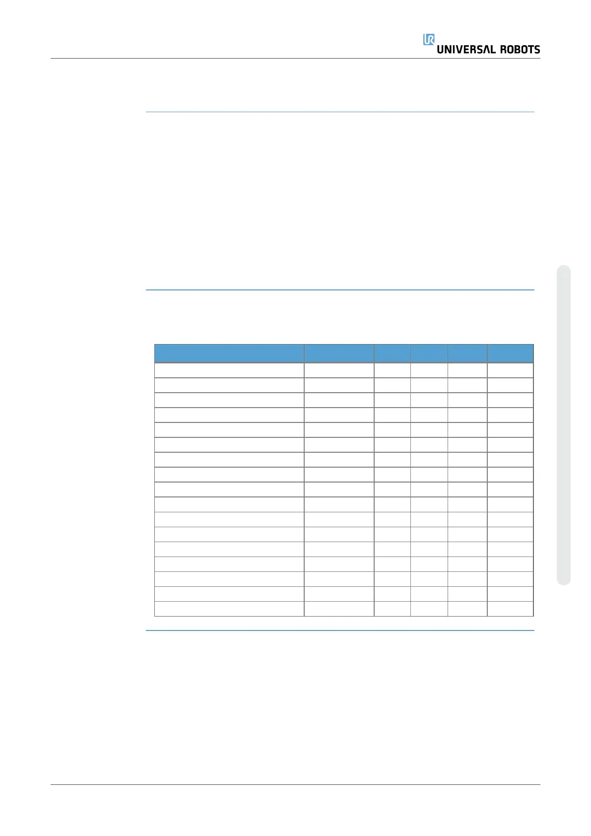
In the GUI you can select input modes (see partPart II PolyScope Manual). The
electrical specifications are shown below.
Terminals Parameter Min Typ Max Unit
Analog Input in current mode
[AIx - AG]
Current 4 - 20 mA
[AIx - AG]
Resistance - 20 - ohm
[AIx - AG]
Resolution - 12 - bit
Analog Input in voltage mode
[AIx - AG]
Voltage 0 - 10 V
[AIx - AG]
Resistance - 10 - Kohm
[AIx - AG]
Resolution - 12 - bit
Analog Output in current mode
[AOx - AG]
Current 4 - 20 mA
[AOx - AG]
Voltage 0 - 24 V
[AOx - AG]
Resolution - 12 - bit
Analog Output in voltage mode
[AOx - AG]
Voltage 0 - 10 V
[AOx - AG]
Current -20 - 20 mA
[AOx - AG]
Resistance - 1 - ohm
[AOx - AG]
Resolution - 12 - bit
User Manual 57 UR10e
4. Electrical Interface
Copyright © 2009–2024 by UniversalRobotsA/S. All rights reserved.

 Loading...


