Engine installation
50
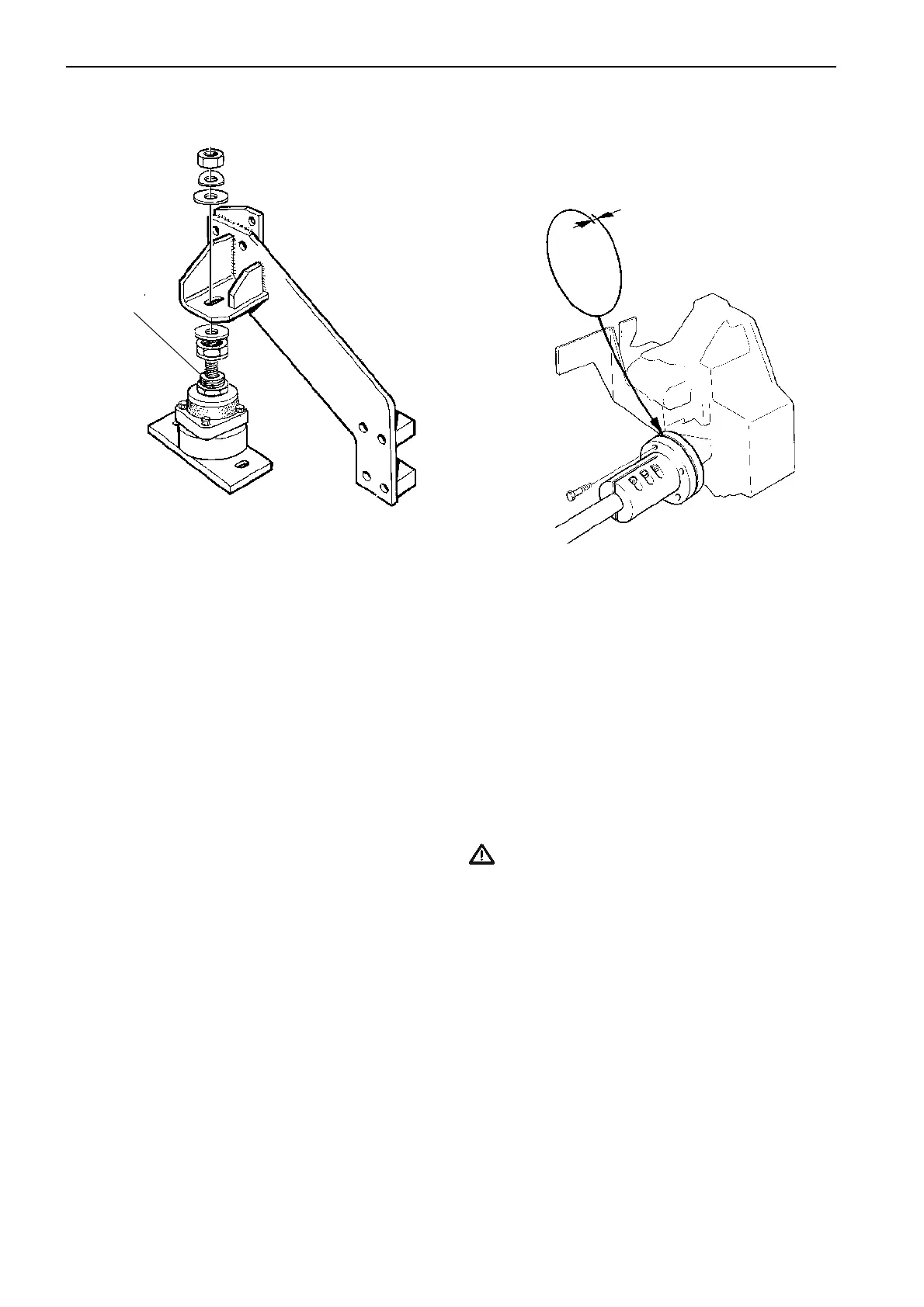
Alignment
Before the propeller shaft is connected to the reverse
gear’s flange, check to make sure that the flanges are
parallel.
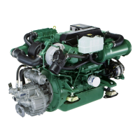
V-drive rubber mounts
Install the rubber mounts for v-drive installations ac-
cording to the figure.
The adjustment sleeve (1) should be tightened
against the mount.
Nominal height for this mount:
106 ± 5 mm (4.2 ± 0.2").
Sideways adjustment:
± 9 mm (± 0.35").
After alignment have been carried out tighten the nut.
Tightening torque: 230 Nm (170 lbf.ft).
Make sure the mount is not adjusted too high. If so a
shim of appropriate thickness must be installed be-
tween the mount and the bed.
Move the flanges together so that the guide engages.
Then, with the flanges pressed together, check that
they are parallel and that a 0.10 mm (0.004") feeler
gauge cannot be inserted anywhere inbetween them
(A). Then turn the flanges 90°, 180° and 270° and re-
peat this check at the new positions. Make sure that
the flanges are well pressed together during the entire
check. If the deviation is greater than 0.10 mm
(0.004"), the alignment must be re-adjusted.
Remove any aids being used and connect the shaft to
the reverse gear’s flange, or flexible coupling.
IMPORTANT! The alignment should be re-
checked again a few days after the launch when
the boat is completed and rigged (sailboats) .
A
1
 Loading...
