Exhaust system
79
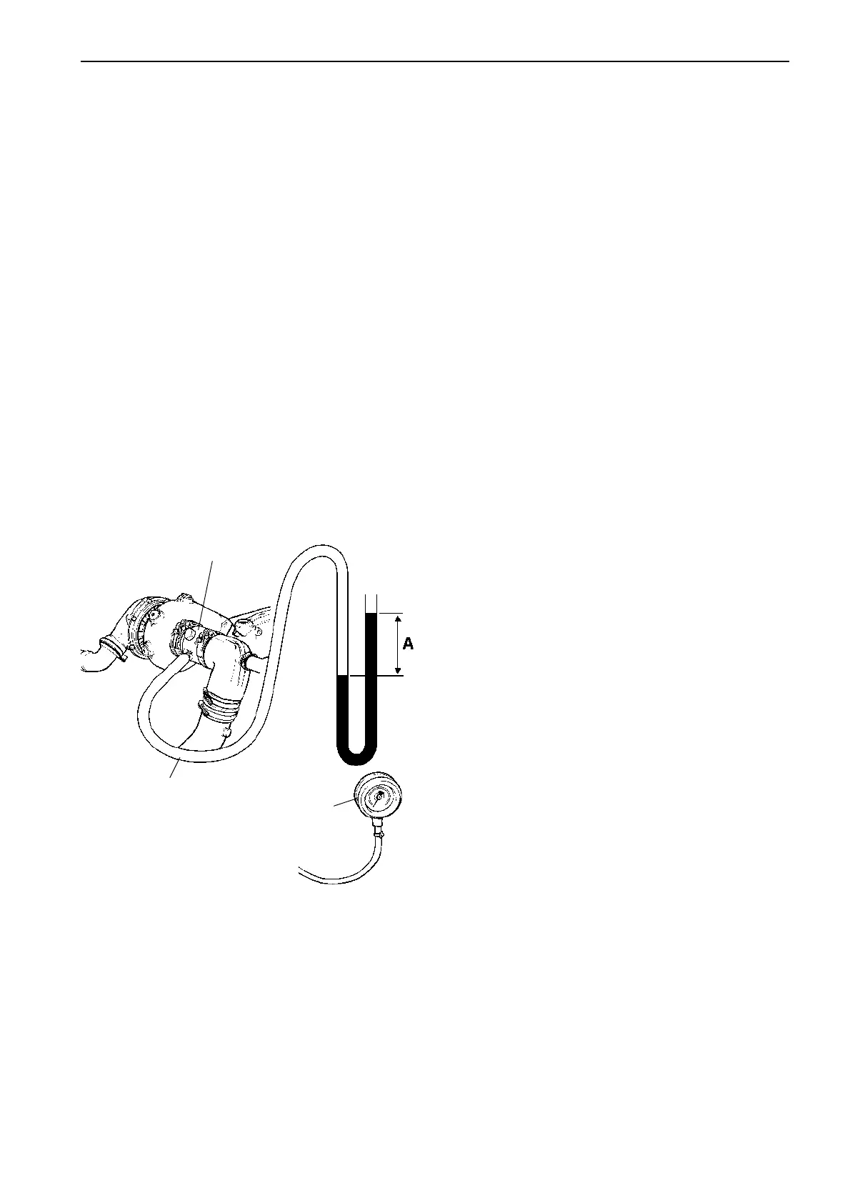
Measuring exhaust backpressure
After the exhaust line has been installed, the back-
pressure must always be checked. This can be easily
done with the aid of a transparent plastic hose con-
nected to a measuring flange special tool no. 885309.
The difference between the water column levels (A) in
figure below, shows the exhaust line back-pressure in
mm or inches water column.
The back-pressure can also be checked with the aid
of a suitable manometer.
When testing is carried out, the engine should be run
under full loading a sufficiently long period to obtain a
stable value.
Measuring procedure
Remove the exhaust pipe from the turbocharger ex-
haust output. Clean the mating surface.
Install the measuring flange 885309 a with V-clamp to
the turbine housing flange. Install the exhaust elbow
pipe on the measuring flange.
Connect manometer 9996065 with pressure hose and
a nipple 9996666 for connection to the measuring
flange.
Alternatively, a transparent plastic hose (2) can be
connected to the measuring flange as illustrated. The
difference between the water columns (A) indicates
the exhaust system backpressure in mm (") water col-
umn.
Run the engine at full load and max. rpm for several
minutes and check that the backpressure is not out-
side permitted values.
Allowed exhaust backpressure in exhaust line: See ta-
ble on page 78.
3
1. Measuring flange 885309 for
connection of plastic hose
2. Transparent plastic hose partly
filled with water
3. Manometer 9996065 and nipple
9996666. Alternative to plastic
hose
A. Exhaust backpressure in mm wc
1
2
 Loading...
