Fuel system
52
NOTE! All tanks must be provided with at least one
baffle plate for each 150 litres (37 US gal) of volume.
Check if there are special restrictions about volumes
and baffle plates.
Filling and venting connections must not be posi-
tioned on the side of the tank.
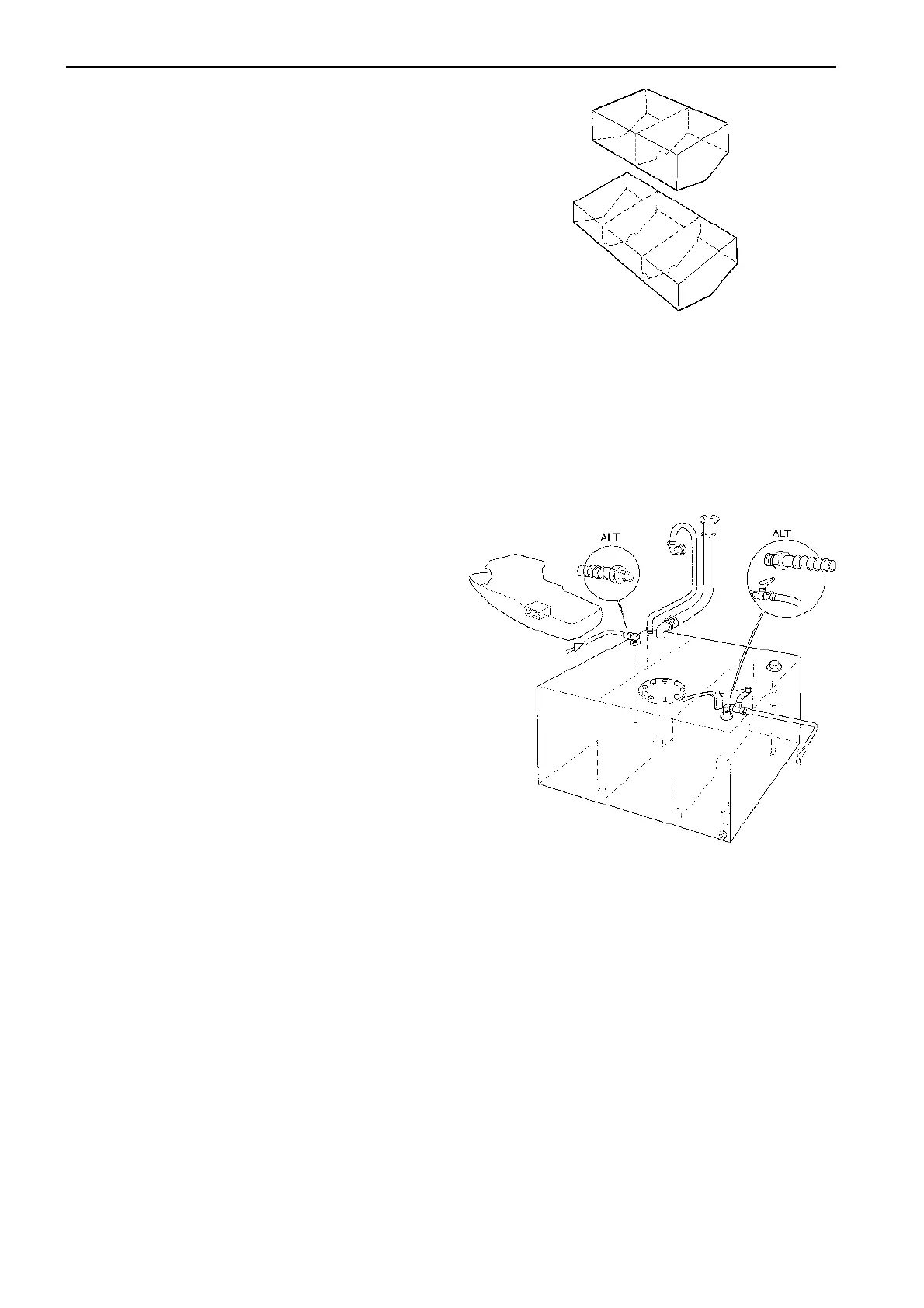
The fuel tank has connections for filling, venting, suc-
tion line, return line, sender for tank gauge and an in-
spection hatch with cover. The suction line and the re-
turn line should be separated as shown in the figure.
A shut-off valve must be installed in the suction line
as close to the tank as possible. The shut-off valve
may have a remote controlled shut-off function by
means of a push-pull cable for example. Certain mar-
kets require electrically controlled shut-off valves.
The fuel return line on diesel engines must be drawn
back to the bottom of the tank in order to avoid air
from entering the fuel system when engine is stopped.
Double tanks should be connected at bottom by
means of pipelines fitted with shut-off cocks. The low-
er connecting pipe should have an internal diameter of
at least 1" so that the tanks can be filled from either
side of the boat. Other fuel tank shapes that are
adapted to the installation geometry are of course ac-
ceptable. Whatever shape is chosen, it is important to
design the tank to provide a low part where water and
sludge can be drained
NOTE! An extra fuel filter with water separator must
be installed for all Volvo Penta engines.
If a day tank is installed, then it is advisable to con-
nect the return line to this tank.
A shut-off valve must be installed in the supply pipe,
between the tank and the filter. This tap should be
able to be shut from a location outside the engine
room.
Stainless steel or aluminum sheet metal is a suitable
material for fuel tanks.
Fuel tanks
If possible, the tanks should be located so that they
are at the same level or somewhat higher than the en-
gine. If they are placed lower, due attention must be
paid to the maximum suction height of the feed pump
which is approx. 1.5 m (5’) for all engines. Note that
the suction height must be calculated from the lower
end of the suction pipe, i.e. 25 mm (1") above the bot-
tom of the tank.
The return pipe should be installed away from the
suction pipe and about 15 mm (0.6") above the tank
bottom to prevent air from entering when the engine is
switched off.
If the tanks are located lower than the level permitted
by the suction height of the fuel feed pump, then the
fuel is to be pumped up to a day tank by means of a
hand pump or power pump. Return fuel from the en-
gine is taken in this case to the day tank.
If the fuel tank maximum level is higher than 3.5 m
above the injection pump on the engine, shut off
valves should be fitted on the fuel and return line. The
valves should be shut off during permanent engine
stop. The maximum static pressure the fuel system
can withstand is 0.5 bar (7.2 psi). There is otherwise
a risk that fuel may leak through the injection pump to
the lubricating system.
 Loading...
