Electrical system
84
EDC–Electronic diesel control,
KAMD44P, KAMD300
Installation instructions, EDC–system, see
Installation EDC–Electronic Diesel Control.
TAMD31/41, KAMD43
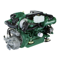
1–pole system:
10. The negative (–) pole on the battery is connected
(earthed) on the flywheel housing.
The positive (+) pole on the battery is connected to
the positive (+) pole on the starter motor
Connections to starter motor
Connecting the battery leads
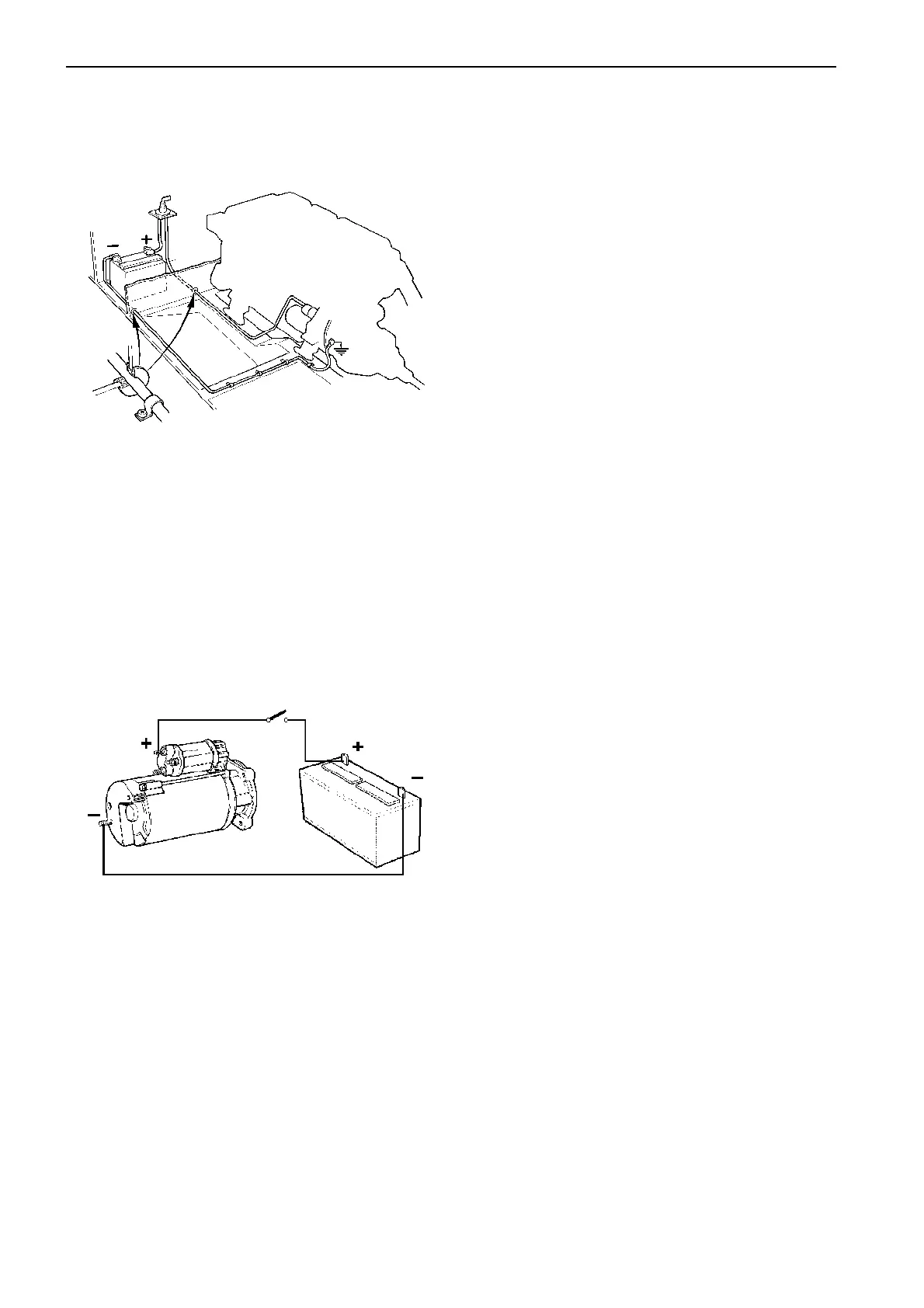
KAMD44, KAMD300
2–pole system, e.g. EDC engines:
11. The negative (-) pole on the battery is connected
to the negative (-) pole on the starter motor.
The positive (+) pole on the battery is connected to
the positive (+) pole on the starter motor.
Dimensions of start battery and cable size, see
Bat-
tery cable area
and table on page 83.
 Loading...
